Week 8 - Challenge 1 - Base Bracket Design
Aim:
To create a Base Bracket Plastic Component through a given Class A Surface and perform Draft Analysis on the final plastic component.
Objectives:
- To Create a Tooling Axis.
- To Create Class B and Class C surface.
- To Create a solid part using surface modelling.
- To Perform Draft Analysis of Class A surface and final plastic component.
TOOLING AXIS:
The Tooling Axis is the direction in which the mould travels. The mold is built in two separate piece named core and cavity.
Three methods for creation of a tooling axis:
- Tooling axis based on x,y,z direction.
- bisecting method.
- normal to the surface.
CLASS-A SURFACE:
It is aesthetic surface and the outer most surface which is visible to the cutomers.
CLASS-B SURFACE:
It is simply off-set of Class A surface and inner most part which is not visible to the customers.
CLASS-C SURFACE:
A surface that joins class-A and class-B surfaces is class-C surface(thickness).
Draft Analysis:
The draft analysis technique is used to analyze whether our part model created in CAD is manufacturable based on the draft condition applied. Where the part should get easily removed from the Mold.
Step-1:
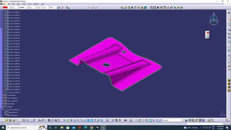
class A input, After join with merging distance 0.1 mm
step-2 creation of a tooling axis:
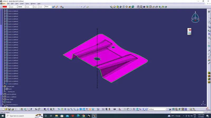
Identify the required and most perfect plane which is suitable for creating a tooling axis.The XY plane is most suitable for the creation of the tooling axis.so,Here we chose Z direction as our tooling axis.
Step -3:
we can now perform the draft analysis on the given class-A surface. before performing the analysis change material property to customizable view parameters.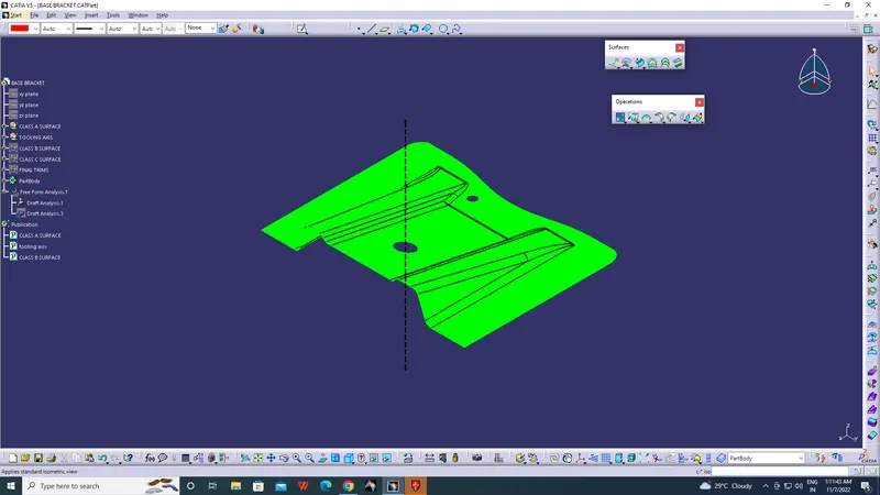
step -4:
creating class B surface
- B surface should be inside the class A surface.
- Class A is an aesthetics surface and class B is an engineering surface.
- B surface can be created by three steps by ribs and the base.
- First step is to create the Ribs by extracting the required surface from Class A and untrim it thus we will get the six individual surfaces and extrapolated all and trim it to get the required shape and finally offset it by the required thickness.
- Then create the base surface by selecting the class A by extracting, offsetting and untrim then extrapolated and offset it.
- The final geometry of B surface is to trim both the ribs and again trim it with the base surface and all together.
- Fillet is given to the required surfaces by measuring the fillet value from the class A surface and the offset value of class B surface.
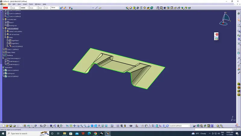
Generating fillets on CLASS B is easy task. But the critical parameter is value of radius to be given.
CLASS B surface is offset from CLASS A, by value equal to part thickness. So there can be two possible types of radius on CLASS B. One is internal radius and the other is External radius with reference to CLASS A surface. Both concept are equally important to design part with uniform wall thickness throughout the component. Detailed explanation can be derived from following slide.
- External radius class B= fillet radius in class A input + component thickness
- Internal radius class B= fillet radius in class A input - component thickness
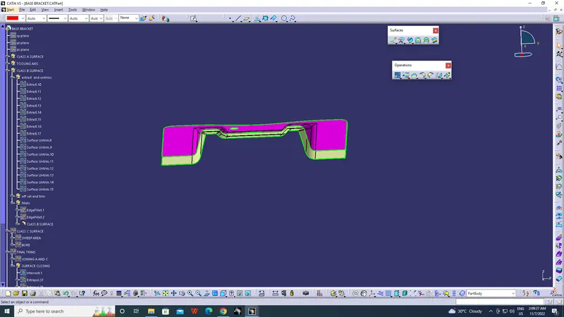
Step-5 :
Creating C surface
- C surface has been created from with reference to the boundary lines of class A surface and sweep it with reference to the tooling axis then the holes are created by following the same method.
- Then join C surfaces and holes with class A surface.
- Finally trimmed the join with B surface to get the final compenent.
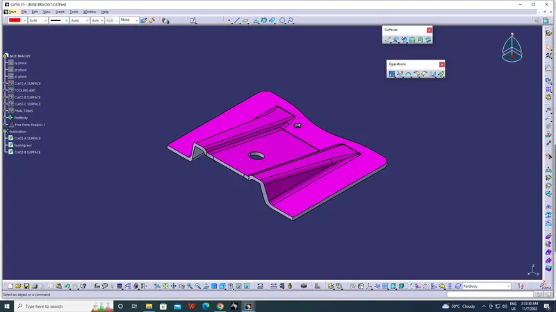
- By using the final Trim Create the solid body by using close surface on part workbench
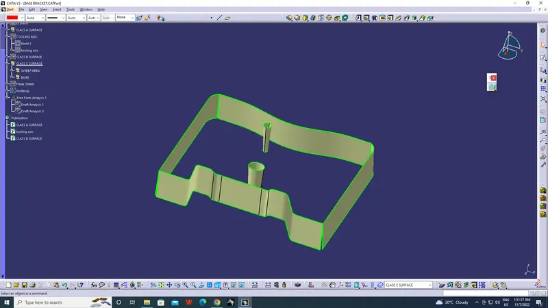
closed surface after trim:
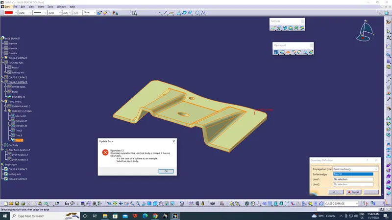
Different views final draft analysis:
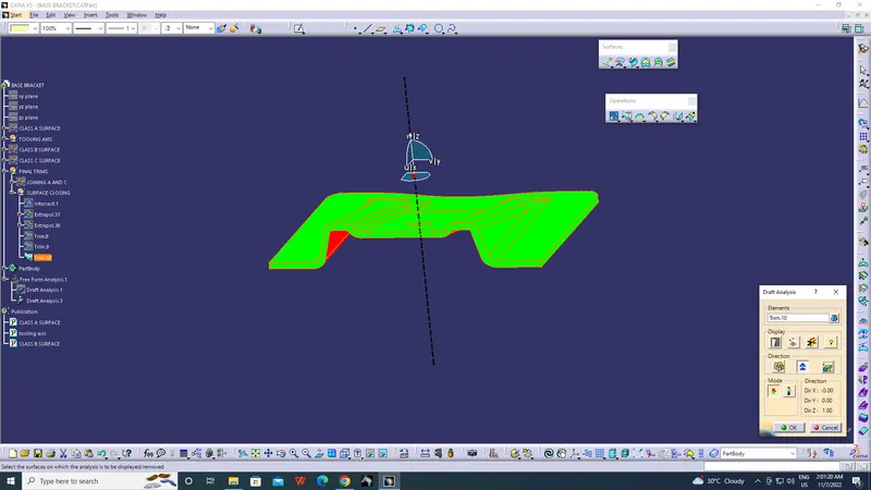
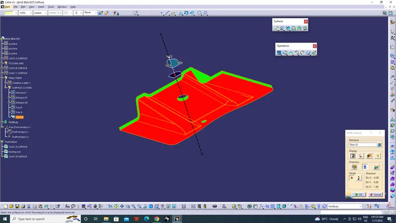
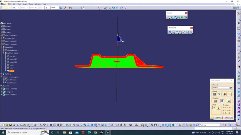
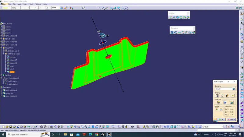
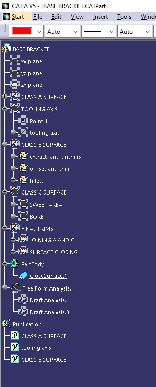
final part body & tree structure:
Material used :
Polyvinyl chloride is used in base bracket.the brackets on the frame that support the engine undergo high static and dynamic stresses as well as huge amount of vibrations. Hence, dissipating the vibrational energy and keeping the stresses under a predetermined level of safety should be achieved by careful designing and analysis of the mount brackets.
CONCLUSION:
Base bracket plastic component using Class A surface have been successfully created and draft analysis have also been performed for the same.