Attachment Feature Creation
ENGINEERING FEATURES CREATION
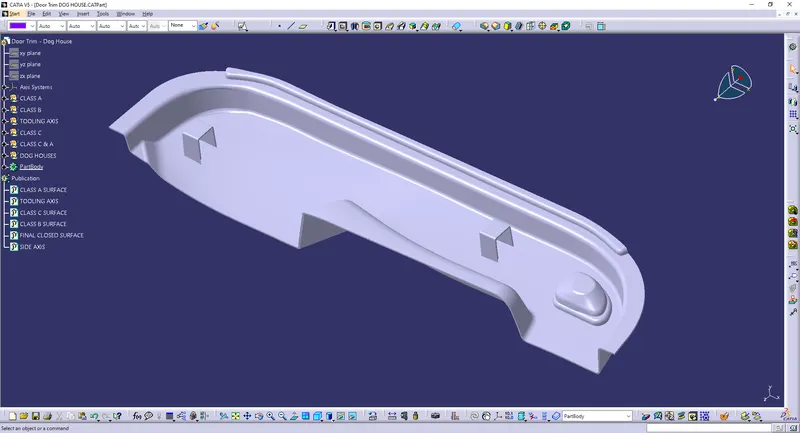
OBJECTIVE: Create dog houses for the door trim considering design rules using Class A surface with the thickness of the component 2.5 mm.
DOG HOUSE:
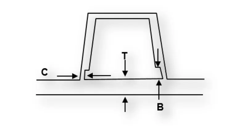
- Dog house is an engineering feature used in plastic trim design as supporting feature.
- A Draft of 1.5 degrees per side is the maximum limit.
- In case of a slide 3 degrees of Draft can be provided
- At the intersection part dog house wall thickness must me less than or equal to 40% of the wall thickness of the component.
- It's height should be between 3 and 6 mm.
TOOLING AXIS:
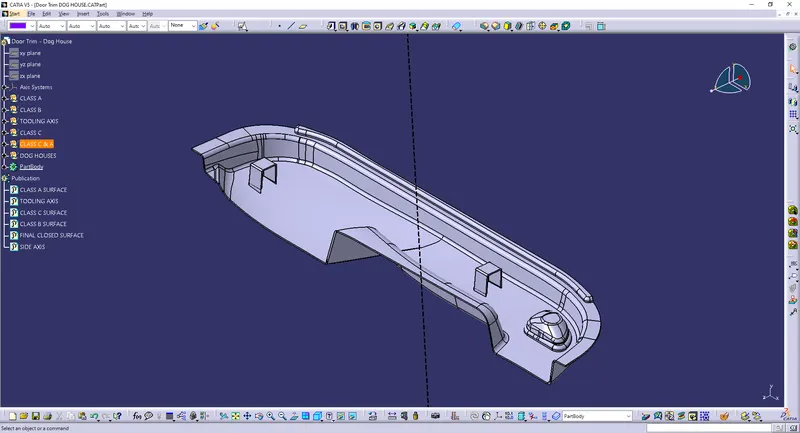
- Considering the Ejection from the cavity of the mould after manufacturing the interior trim must have the nominal 3-degree draft angle.
- Hence the tooling axis is created by considering the above factor.
- The direction in which the mold or core and cavity opens is the tooling axis.
- In this case below is the tooling axis that I have used.
- The Line in the black color is our tooling axis.
SIDE AXIS:
CLASS A SURFACE:
- In automotive design, a class A surface is any of a set of freeform surfaces of high efficiency and quality.
- It is the visible aesthetic surface of any automotive component.
- Class A surface refers to those surfaces which are visible and abide to the physical meaning, in a product.
- This classification is primarily used in the automotive and increasingly in consumer goods industry.
- It is a requirement where aesthetics has a significant contribution.
- For this reason, the exterior of automobiles is deemed Class-A.
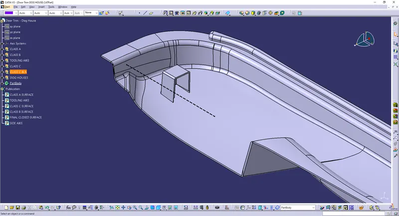
- Below is the CLASS SURFACE that I have used for this model.
CLASS B SURFACE:
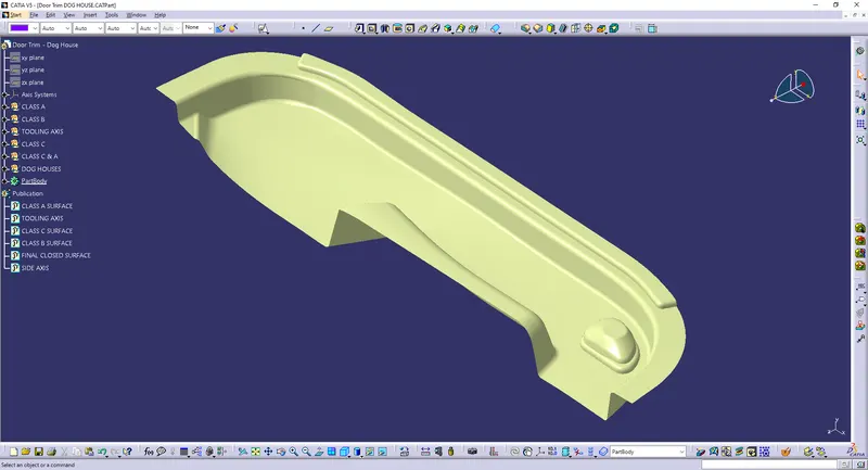
- Class B surfaces are Engineering Surfaces which are invisible to the eyes or often on the back side of the Class A surfaces.
- It is mainly the thickness of the component or Class A.
- These surfaces need to be designed as per the Class A surface i.e., the continuity, thickness of the component, functionality etc should be maintained.
- These surfaces include the main engineering features such as Screw bosses, Ribs, Snaps, Stiffeners and fixations.
- B surfaces also do not contain any aesthetic styling content and textures since it is not visible to eyes.
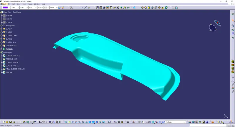
- Below is the image of CLASS B that I have created.
CLASS C SURFACE:
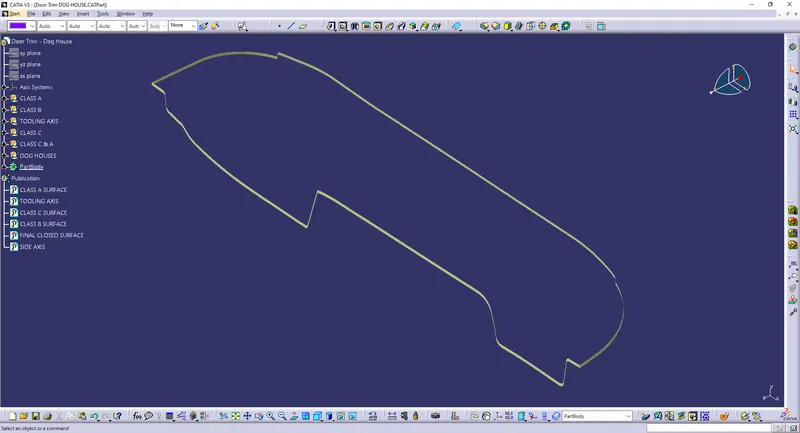
- Class C surfaces are connectors between Class A and B surfaces.
- This surface connects both A and B surfaces along the Tooling Axis.
- It contains the draft as per the design.
- It is basically the thickened surface between both A and B surface.
- Below is the Class C surface that I have created for this model.
CLOSED SURFACE:
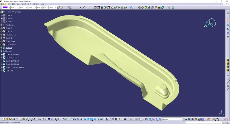
- Now the class – A and Class- C surfaces were joined together by removing the gaps in-between them with the help of extrapolation and Trim surface.
- Then, by defining the part body by using the Closed Surface command in Part Design, the component's solid body is created.
FINAL SOLID BODY:
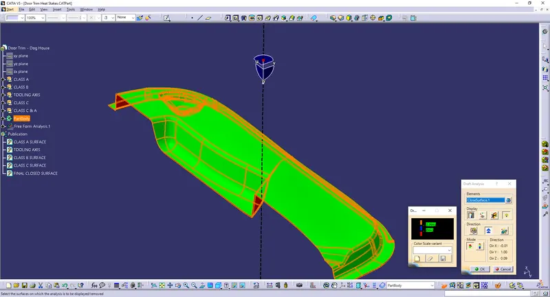
DRAFT ANALYSIS:
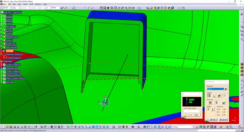
- Draft Analysis is a tool in CATIA which identifies the zones which deviates from the specified values of angles along a defined draft direction using colour codes.
- It highlights the regions of draft using colours.
- Draft analysis is the first step performed after receiving the Class A of the component.
- Draft analysis should be passed in order to make the plastic component manufacturable.
- Acceptable draft angles are used as range for draft analysis that is 0 to 3 degree.
- For Heat Stakes draft given is 0.5 to 2 degree.
CONCLUSION:
This reports concludes the creation of DOG HOUSES by following all Design Consideration for this DOOR TRIM.