Week 9 - Attachment Feature Creation - Challenge 2
|
AIM: To Design the Dog House for the Door Trim considering the relevant design rules. Perform draft analysis on the final component and analyze the results. Objective:
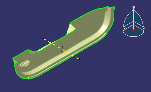
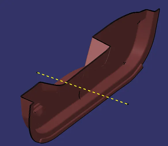
Creation of the tooling Axis: The given input Class-A surface is checked for any surface defects or discontinuities. This can be checked by using the ‘boundary’ or ‘join’ feature in the ‘Generative Shape Design’ workbench. Since there were no such defects found in the class-A surface, the tooling axis is created. To create the tooling axis the given input is carefully analyzed visually and the most suitable direction is selected such that there are minimum or no surface that can obstruct the tooling. From the given input, the tooling axis can be created in the y-direction. The tooling axis is usually created by the bisection method but in this case, the tooling axis is just a line normal to the surface in the y-direction.
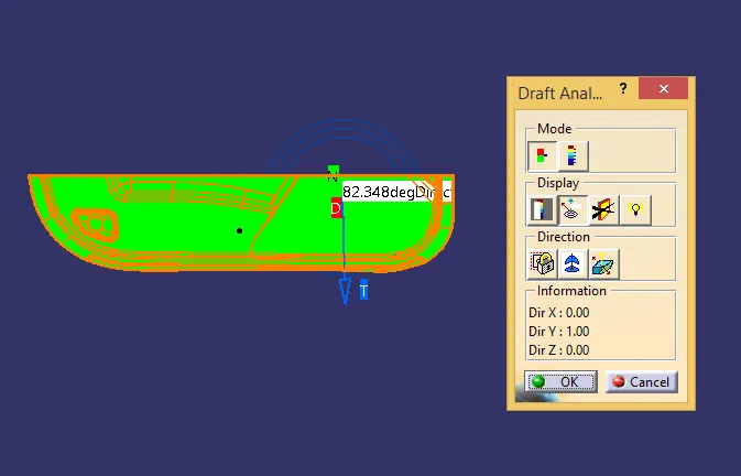
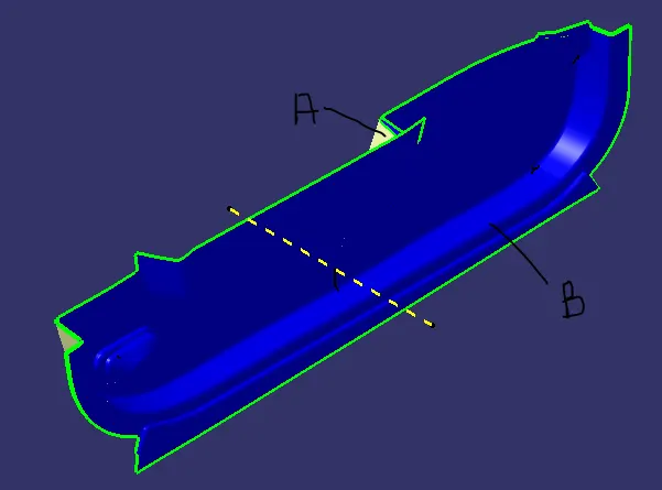
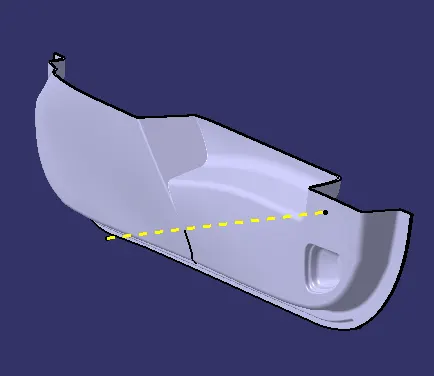
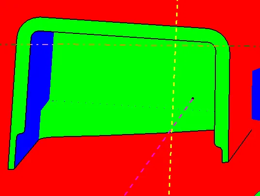
Draft Analysis on the Class-A surface: To carry out the draft analysis on the given class-A, the viewing mode should be kept in the ‘material’ mode and then select the ‘Feature Draft Analysis’ option under analysis section in the ‘Insert’ tab. Then place the compass along the tooling axis created and click on the class-A surface. Then the draft report is shown through color gradients on the class-A according to the specified draft value. By this color gradient it can be easily analyzed that the given class-A passes the tooling in the considered direction. Creation of B surface: To create the B surface, the selective surfaces form the class-A are extracted using ‘multiple extract’ command and then are extrapolated to the relevant extent. The all the extracted surface are trimmed and the resulting surface is offset to the required thickness value of the component, i.e., 2.5mm. Then another set of surface are extracted, extrapolated, trimmed, offset from the given class-A. Then the individual offset surfaces from multiple actions are extrapolated and trimmed off to arrive at the required class-B surface.
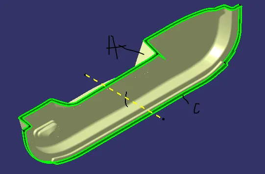
Creation of C Surface: The C surface is created with the help of the input class-A surface. To create the C surface, the edge of the class-A is extracted in fragments using the ‘multiple extract’ command and then is swept with respect to the tooling axis with the relevant draft angle using the ‘sweep’ command to the required length. Then all the swept fragments are joined together by either joining or trimming the unwanted surface. The surface obtained as a result is the required C surface.
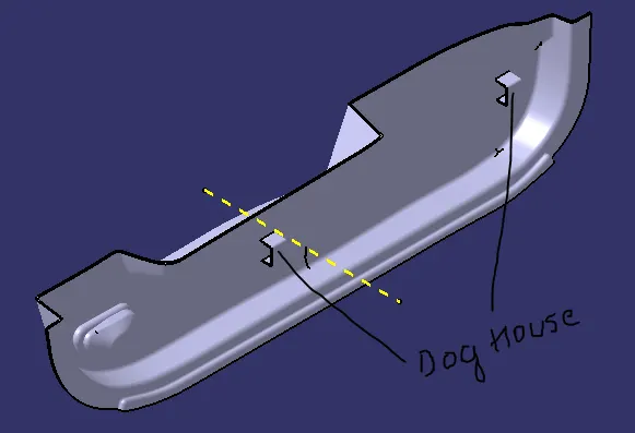
Creating Solid Component: To create a solid component, first we need to obtain the closed surface consisting of the class-A, B and C surfaces trimmed off depicting the actual component so that the obtained surface is the hollow representation of the actual component. Then this hollow surface is filled using the ‘close surface’ feature in the ‘Part Design’ workbench. The closed CAD component obtained is the required model of the component. Creating Dog House Feature: To create the dog house feature, first a reference surface is extract from the component and then a sketch is created on the surface. Then the sketch is extruded in the ‘Generative Shape Design’ surface workbench. Then the relevant thickness for the feature is provided in the ‘Part Design’ workbench. Later the feature is provided with fillets and then is added to the base component body using the Boolean operation. Similarly another Dog House is created at the relevant position on the B-side of the component in a similar manner or the first one can be translated to the required position.
Draft Analysis on the Feature: Finally the draft analysis on the overall plastic component is carried out in a similar manner as done on the class-A surface. And for the dog house feature, the draft analysis should be carried out along a different tooling direction as it required a side core to manufacture. So a new side-core axis is created which is perpendicular to the initial tooling axis and similar procedure as above is carried out for draft analysis of the dog house feature along the side core axis.
|