Week 9 - Attachment Feature Creation - Challenge 2
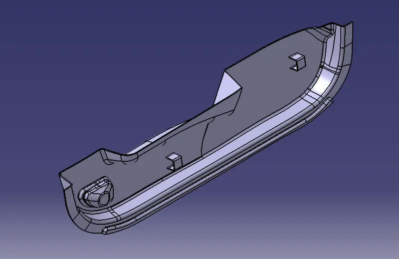
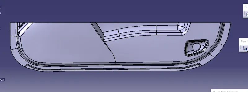
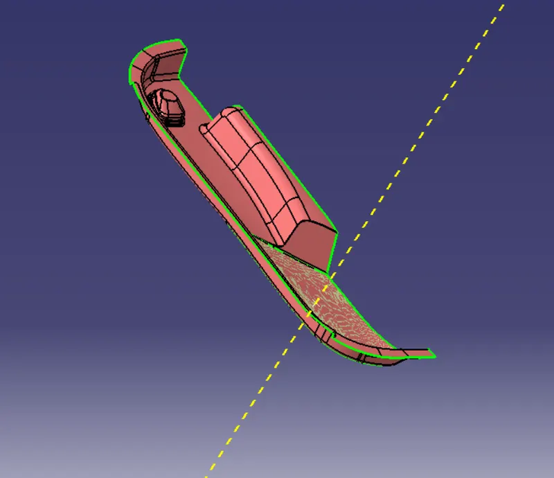
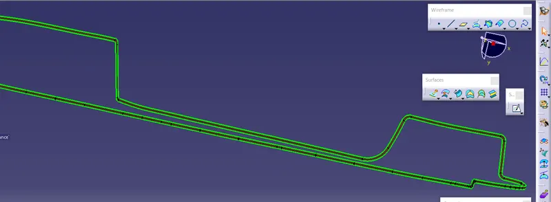
We have recived input as Door trim , so our 1st step is check the connectivity of Class A surface using boundary command
Since their is no gap so we can move to 1st step
Step-1 Selection Of Tooling Axis
Tooling Axis-The direction in which core and cavity open is tooling axis.
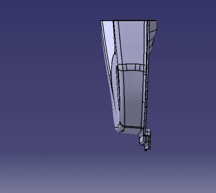
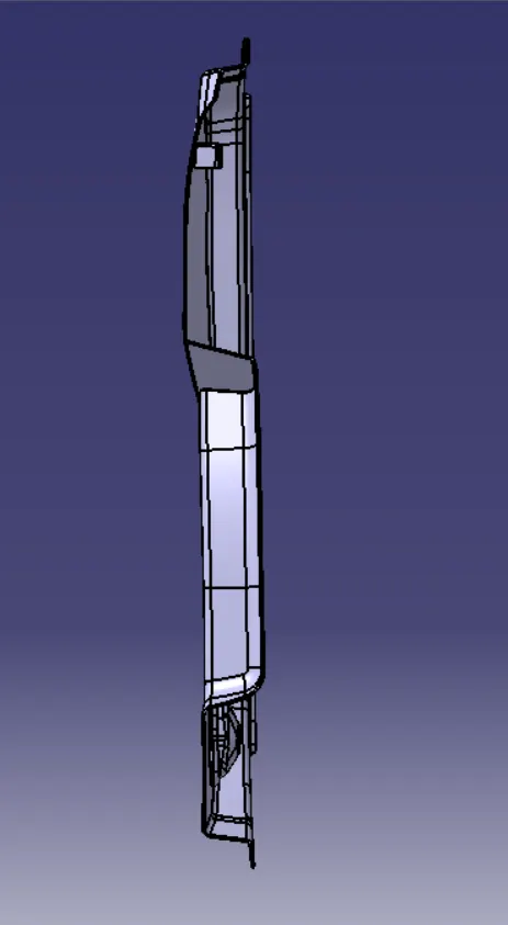
- So after visualising, we can say that Y-direction is tooling Axis direction.
- I have selected lower flat face of the Class A surface and extract it.
- MAke a point on extract surface.
- Make a line passing through point and normal to surface.
- This is our tooling axis.
Step- 2 Draft analysis for CLASS A -Surface
- Insert > Analysis > Features draft analysis
- Make sure view mode Customization to Material mode
- Now go to direction, and click 2nd option.
- Pick the compass and align it with the tooling Axis and click on the lock .
- Now click on the class A surface,here we notice there are some part when our draft angle is 2.9 degree.
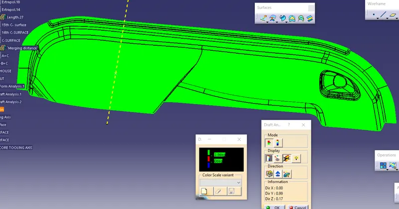
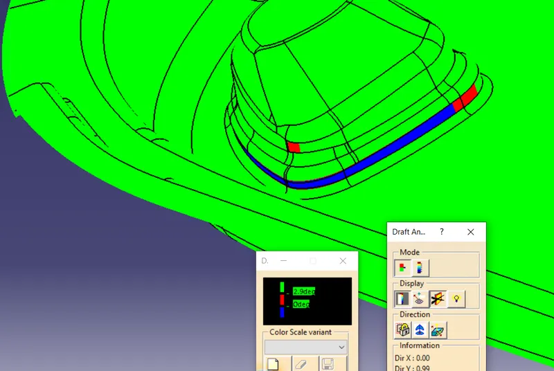
This is happening becausing some face of class A surface is not given proper draft angle.
Step-3 Class-B Surface
- Offset the class A , 2.5mm.
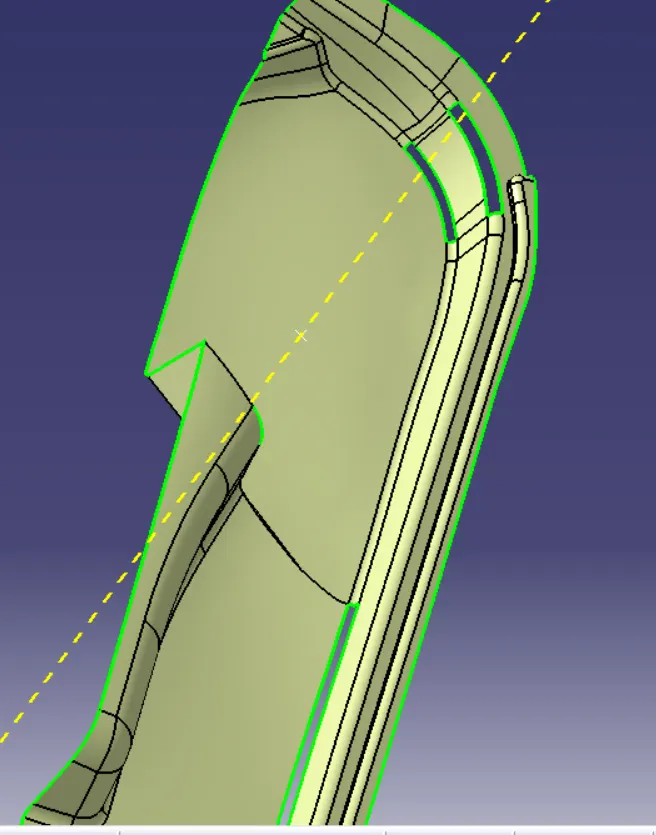
- We notice there are 4 patches.
- I have used 2 methods to fill these area (Multi-section surface and extrapolate trim method)
- So first i used multiple extarct and selected the above fillets and turn on complementary mode(as shown below image)
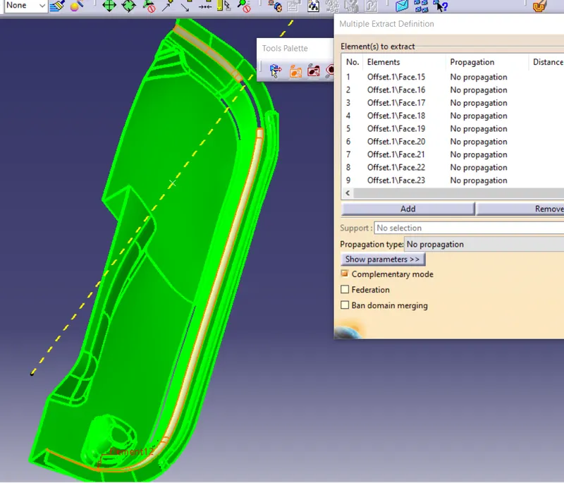
- Now i have disassemble the multile extract, i got 2 surface.
- Extract the boundary of both surface , from fillets side.
- Now i have used extrapolate on both surface, from fillets side.
- Now I have used trim and applied the fillets, so our top patch is filled.
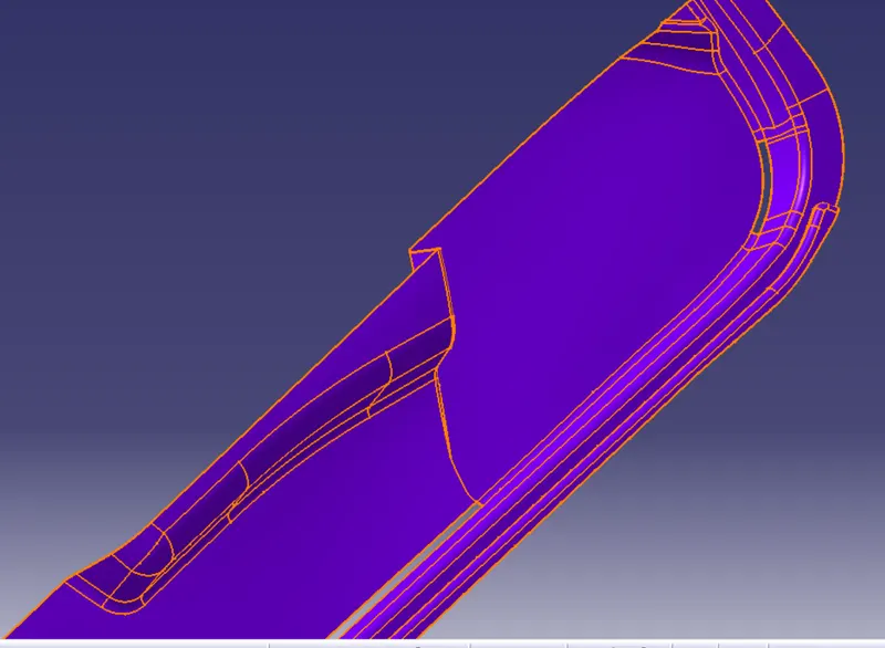
- Now in remaining area I have used multi-section surface.
- So i have extracted the boundary, useing the Milti Section Surface.
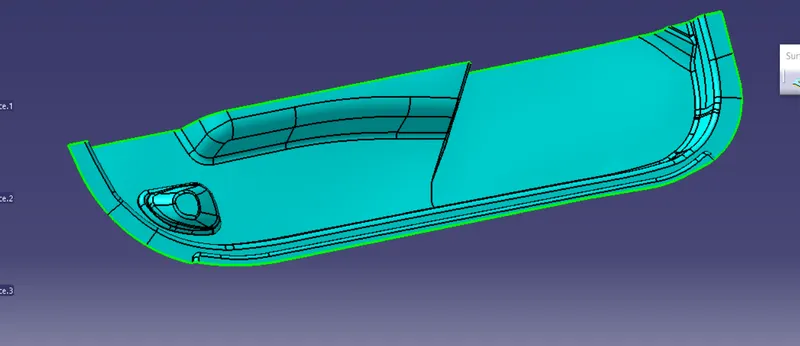
- Join them all and our B- surface is ready.
B-SURFACE
STEP 4 - CREATING C-SURFACE
- To create C -surface i have used both sweeep using draft direction and reference surface.
- To C- surafce near fillets i have used Multi-section surface.
- Also i have taken some points on egdes of Class A surface so that i can create my C-surface easily.
- I have divided surface into many parts and in the last in trim them and join together.
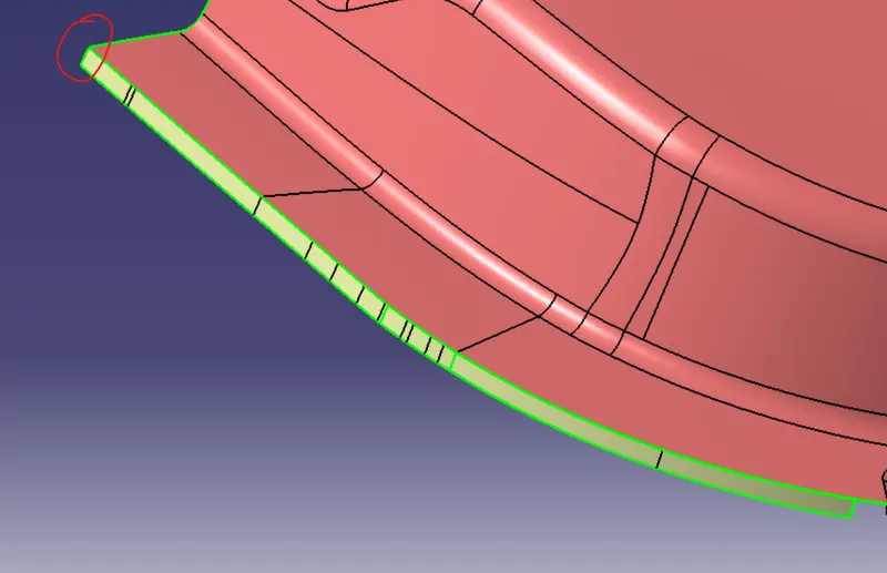
- In the above Class C - surface , I have used sweep using reference surface and middle area i have used MSS.
- Also the area i mark with red colour , i have extrapolate it so that it can intersect other side C- surface.
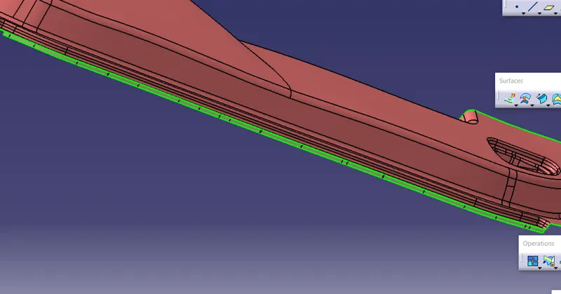
- Now i have used sweep using draft direction , since tis whole c- direction is pallel to draft direction
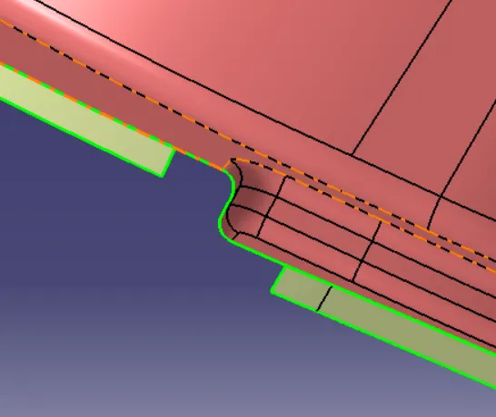
- Now to fill this fillet i have used multi-section surface,
- Also we can notice that the the egdes of both C-surface are straight line , so the MSS was not happenig proper because of this, so to to solve this i have used split and cut some part of ONE C surface as shown in below image.
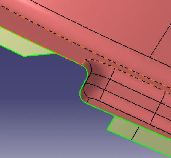
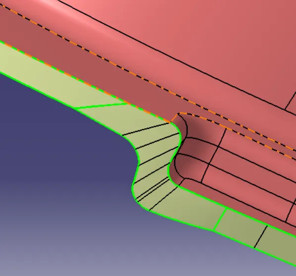
- Now i have used MSS.
- I have done same thing other side.
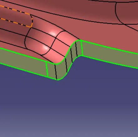
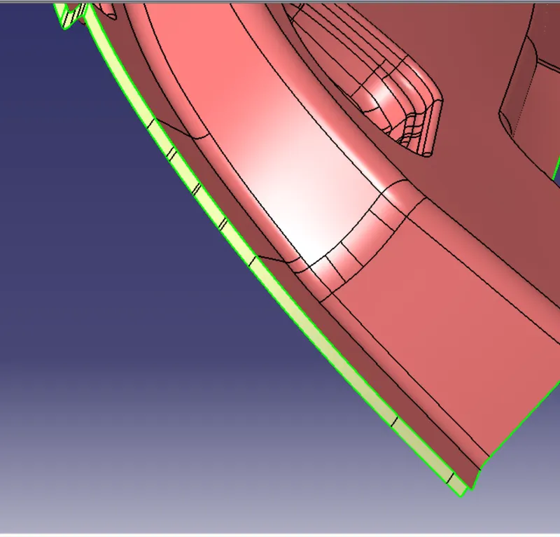
- The above C-surface I have used Sweep using draft direction and in corner i am extrapulated it 2mm
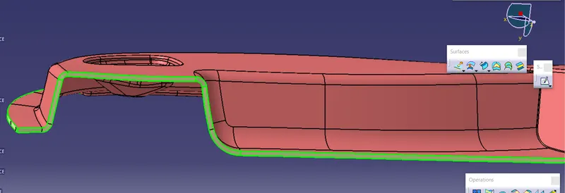
- Now here the if the direction is C-surface parallel to tooling axis I have used sweep Using draft direction and if not i have used sweep using reference surfsce
- And the fillets area i gave used MSS.
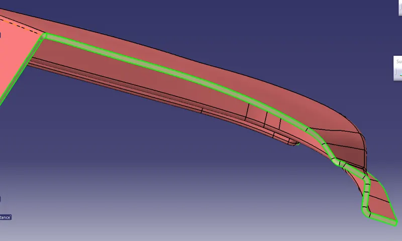
- This part is done using sweep using refence surface.
- I have take angles as 93degree or 3degree.
- Then i join them all
C-SURFACE
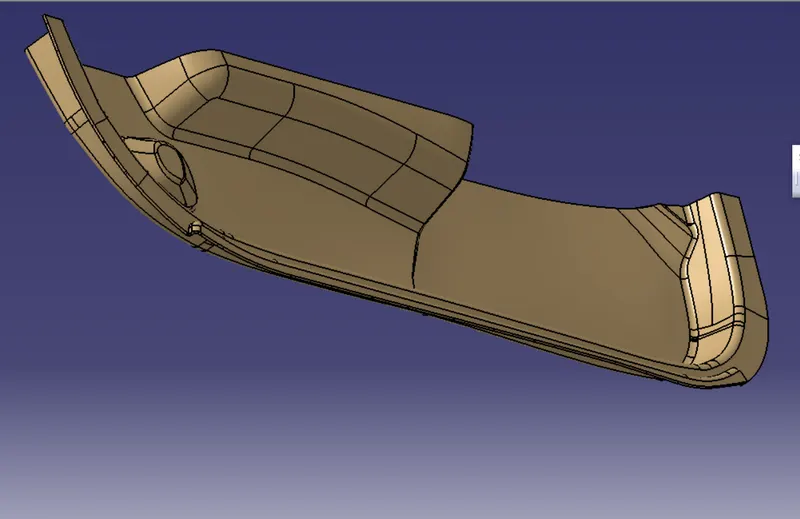
- Join C -surface with A-surface.
- And trim with B surface(extrapulate B- surface = 2mm )
A+B+C SURFACE
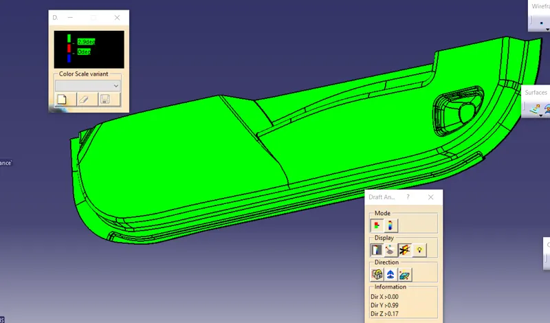
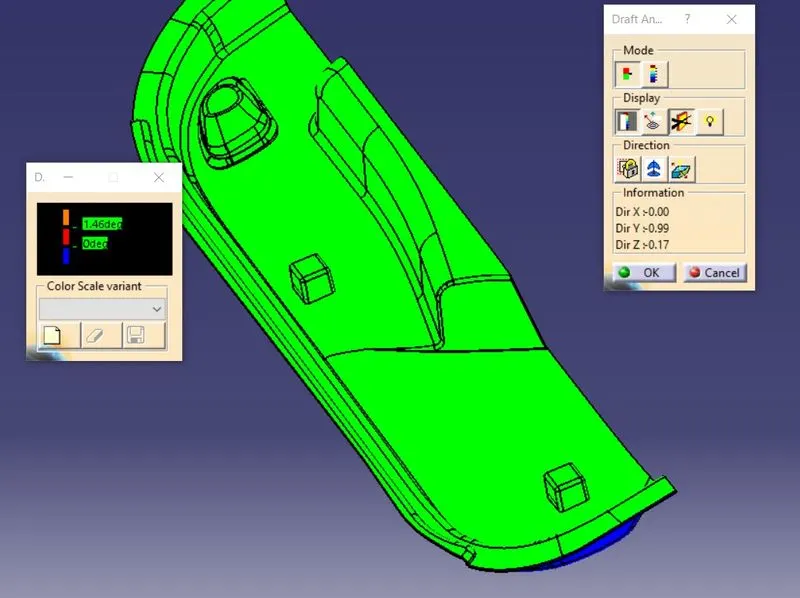
Step-5 Draft analysis report for the final plastic component
Draft analysis tell whether our component is manufacturable or not, if it's green it clears but if it's red means the surface is not clearing.
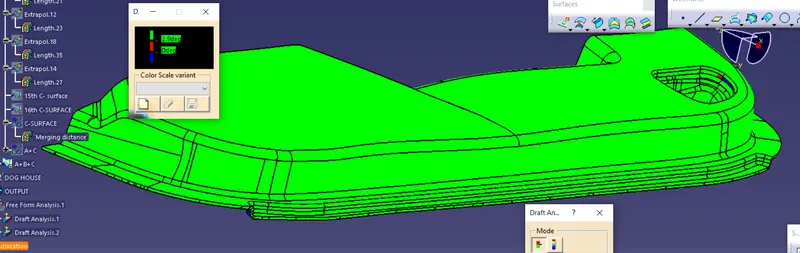
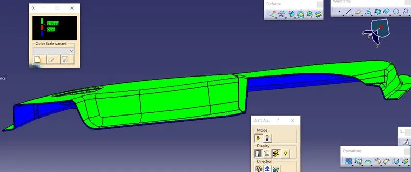
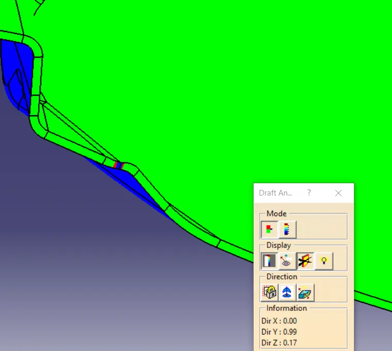
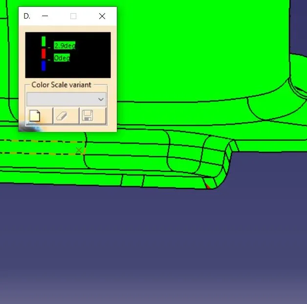
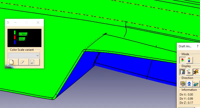
In this area i have used MSS because of fillets ,So i was not able clear a very small area of class C- surface.
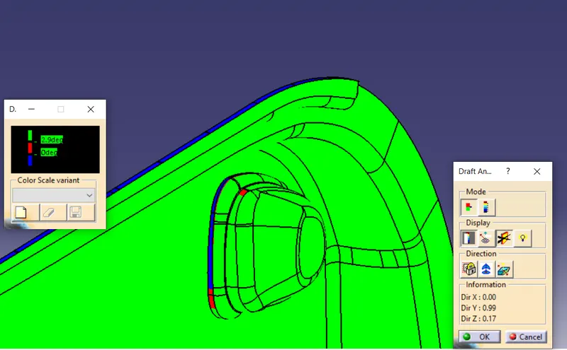
This area is not clearing because of Class -A surface is not drafted properly.
Step-6 DOG HOUSE CONSTRUCTION
DOG HOUSE- A dog house is a feature that is used
- to avoid sink marks
- solve length issue of screw boss
- and with the dog house we can make screw boss perpendicular to tooling axis
DIMENSIONS OF DOG HOUSE
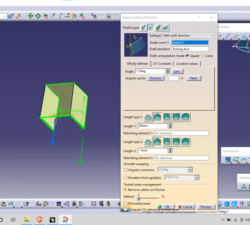
- Draft angle for main tooling Axis= 1.5degree
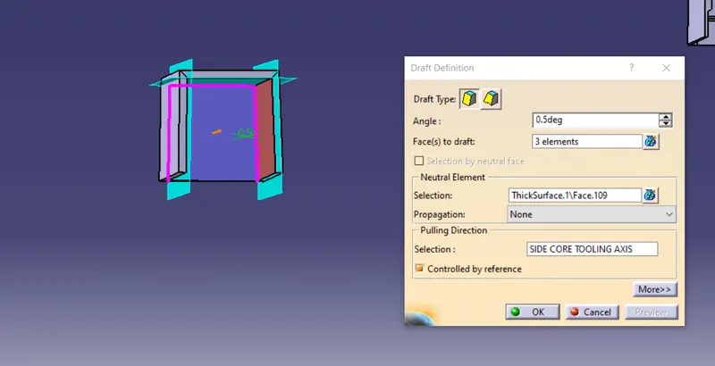
- Draft angle for side Tooling Axis= 0.5degree
- C = 1mm (0.807 to 1 mm)
- B= 4-6mm from surface (Since our surface is not flat it will vary)
CONSTRUCTION
- I have extract a surface and made a point on it
- Now i made a plane tangent to extract and on that point
- Make a sketch as shown in below image
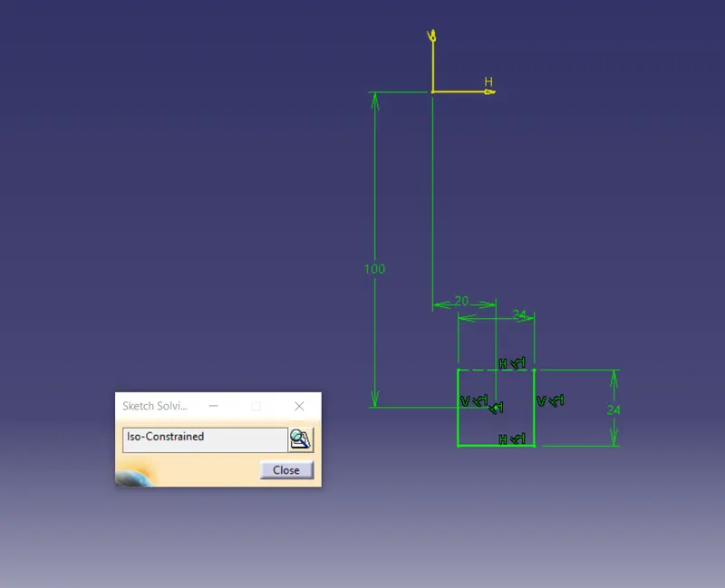
- Sweep the sketch using draft direction and a take direction as tooling axis(1.5degree)
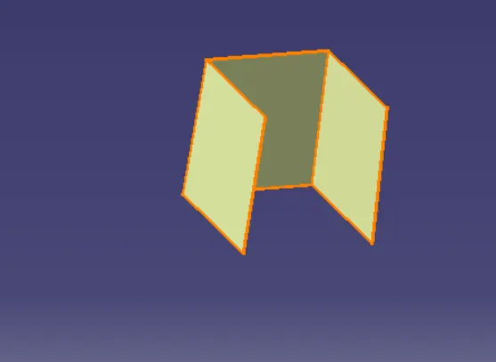
- Use Multi - Section to fill above surface and join them.
- use thick surface
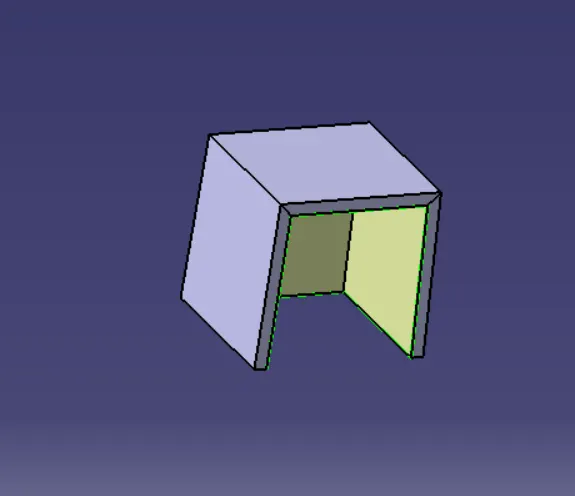
- Since we done sweep using draft diection so we have already provided draft in tooling direction.
- so now we will provide draft for side tooling axis.
CREATION OF SIDE TOOLING AXIS
- Extract the inner middle face of the dog house.
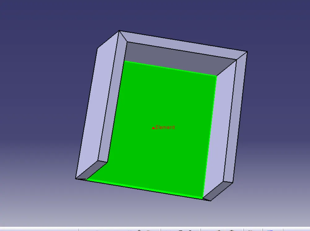
- Now make a point on this extract and draw a line on that point and normal to extract.
- this will be our Side core Tooling axis.
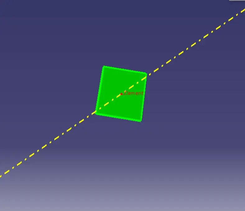
- Now we have to give draft for side core tooling axis inside dog house.
- So we have selected the face and provide the draft as shown in below image
- Provide the fillets
FOR LOWER THICKNESS C
- Extract the avove surface of dog hose and extrapolate it
- now offset in downward direction 20mm.
- Now extract inner surface
- Offset 1mm and extrapolate it (below image).
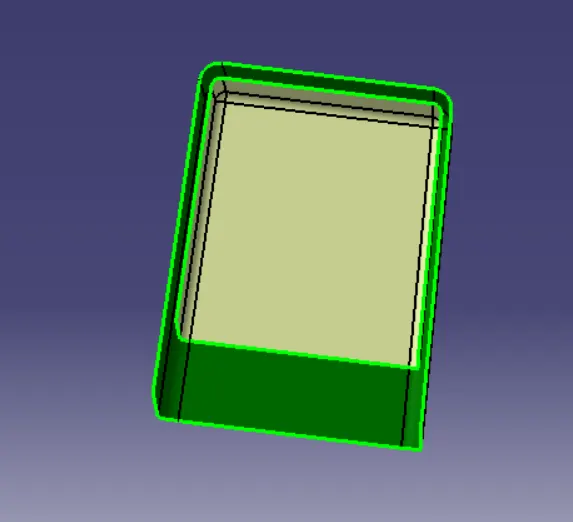
- Now we have to trim this extrapolate with above offset.
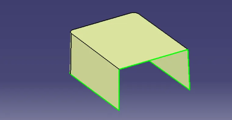
- Now in part workbench , define the dog house body
- use split and select above trim as splitting element.
- Privide fillets and dog hose is ready.
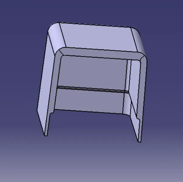
- To make other trim house, I have used translation feature.
- I extract the face in which I have to create dog house, and offset it 1 mm,
- Made a point and used translation (point to point).
STEP-7 Draft analysis report for the DOG HOUSE
For SIDE CORE TOOLING AXIS- My inner face and outer boundary are green so it will be clear in Side core tooling axis.
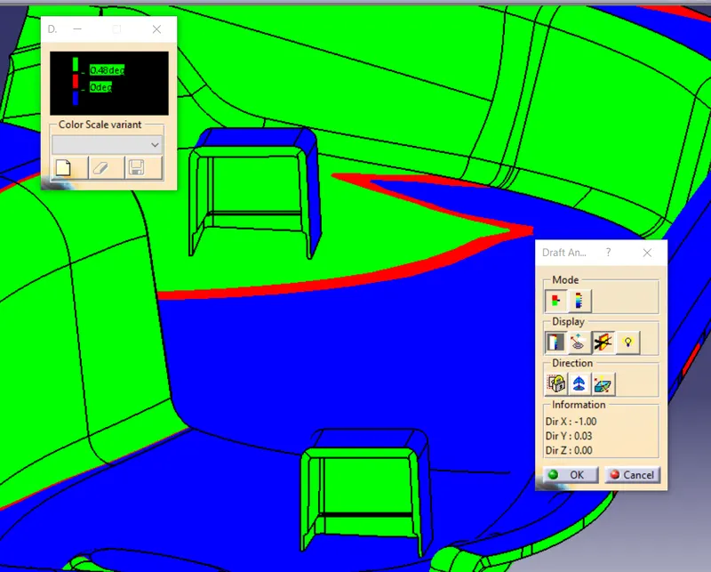
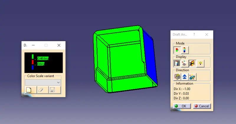
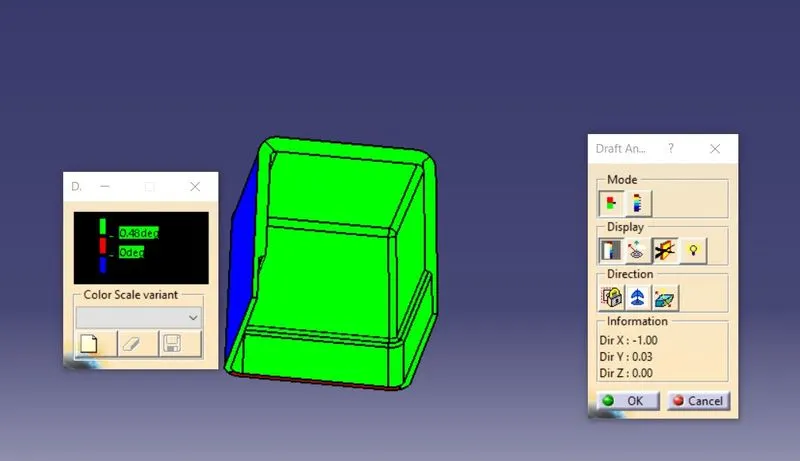
2nd dog House
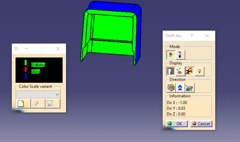
FOR MAIN TOOLIN AXIS - My outer face are green so it will be clearing with main tooling axis.
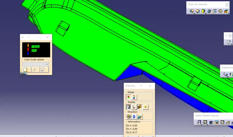
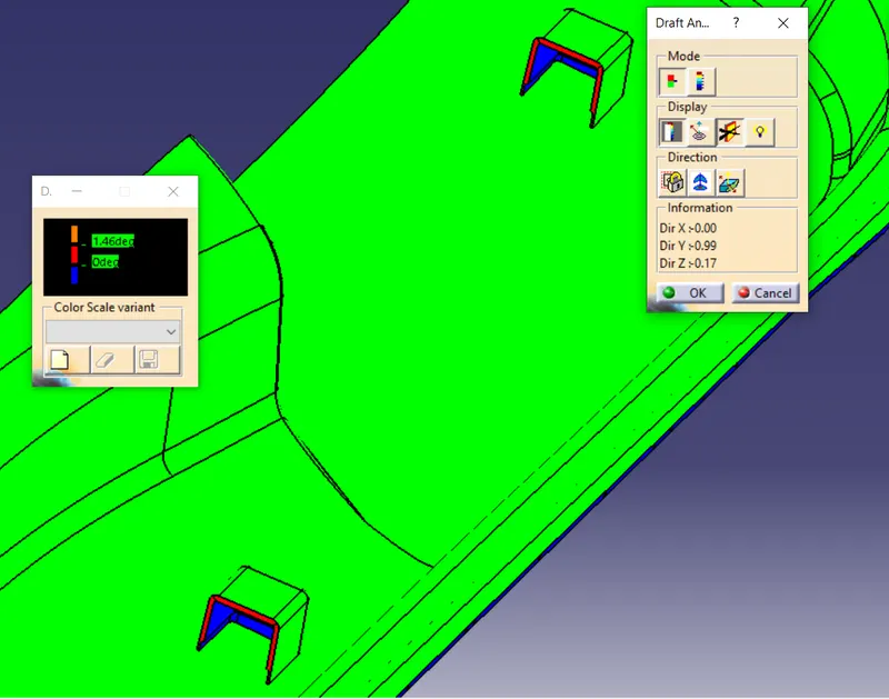
This red boundary will be clearing side core tooling axis.
VIEWS