Week 8 - Challenge 1 - Base Bracket Design
- Report
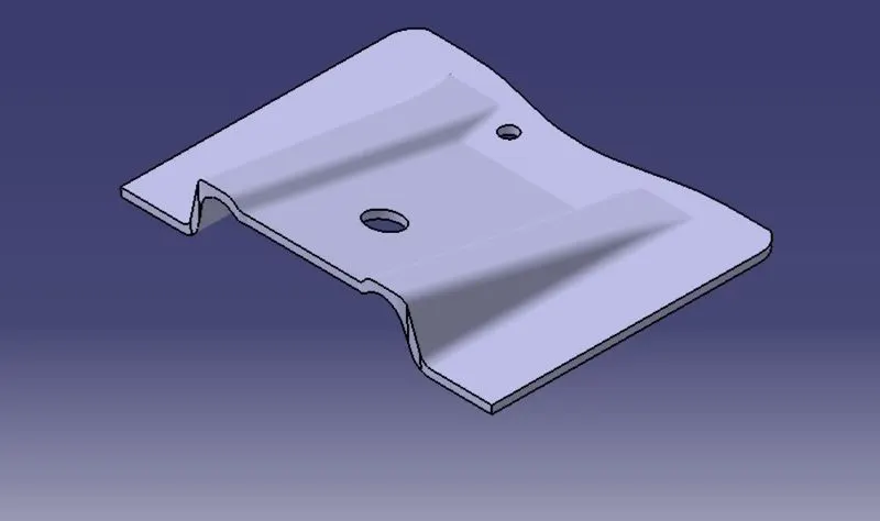
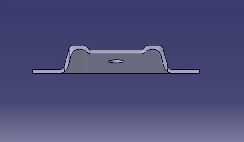
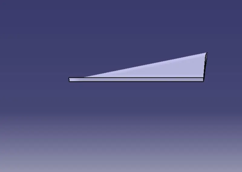
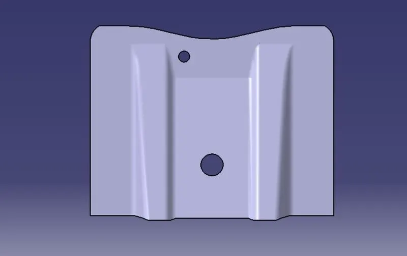
We have input as an class A Surface.
Step1-
So our first task is check continuity of class A surface using boundary or join command.As there is no gap between components so it clear 1st step.
STEP-2 TOOLING AXIS
After visualizing class A surface we can concude this
- Along x direction it possible but due to hole it will be very expensive.
- Along y direction it is not possible.
- Along Z direction holes wcan easily clear, so z is tooling axis.
CREATING TOOLIN AXIS
- create a dummy axis along z direction(at centre of any circle)
- ZX will not create any problem.
- So,now Intersect ZY plane to class A surface(centre of circles).
- From figure(1) we can say that most line (surface) will not create problems other than 2 highlighted lines.
- Now we will extend both the line and take their bisect ,so the bisector of 2 lines will be our tooling axis.
FIGURE -1
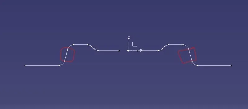
FIGURE-2(EXTENDED LINE WITH TOOLING AXIS)
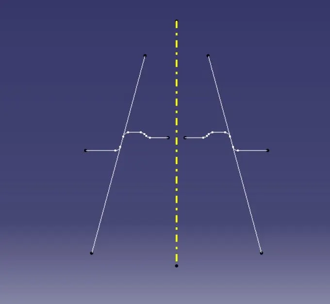
So while creating a tooling Axis using bisecting methods, we create a bisecting line which clears x direction and other bisecting line which clears y direction. After that the bisector of these both line will give us a tooling Axis.
Here we have only took one bisector because as we can se our surface was clear x direction.
For draft analysis.
- For draft analysis go to
- Insert > Analysis > Features draft analysis
- (Make sure it should be in material mode)
- Now go to direction, and click 2nd option.
- Pick the compass and align it with the tooling Axis and click on the lock .
- Now click on the class A surface,we will see a green colour surface.
- Now give 3° draft.
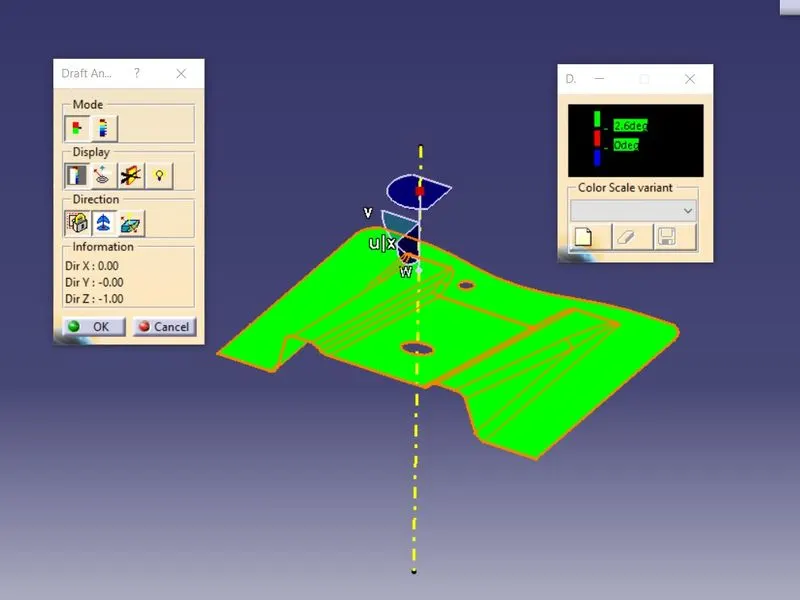
Draft analysis report for the final plastic component
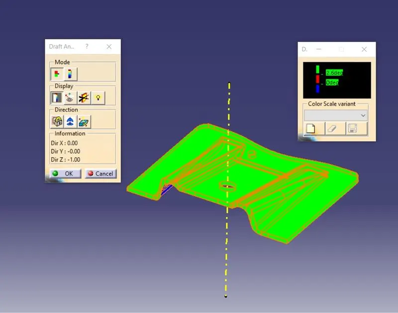
views