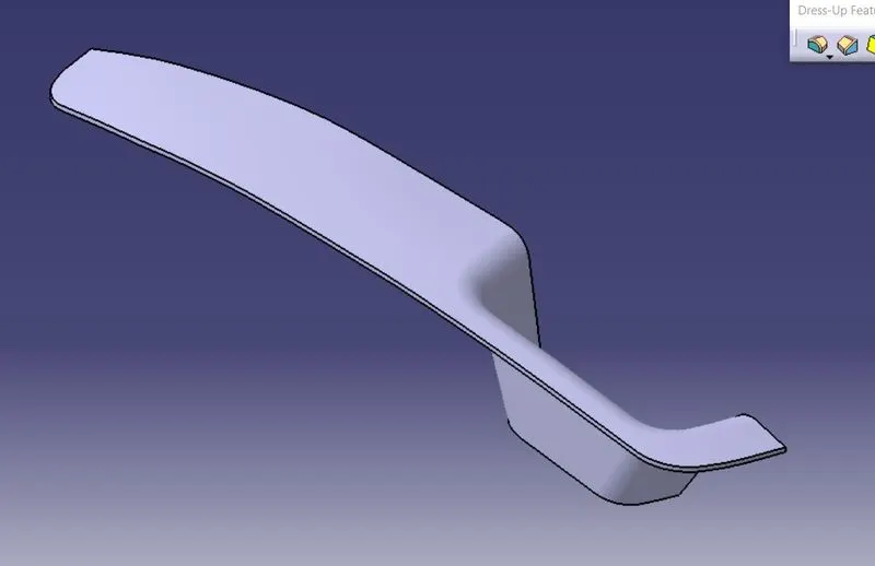
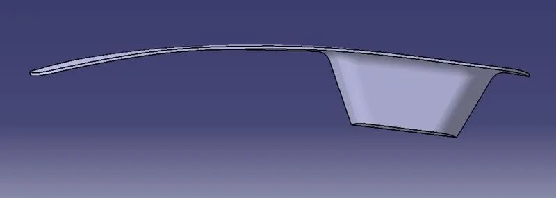
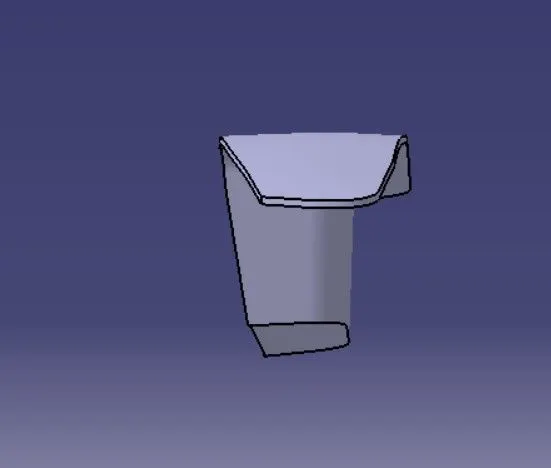
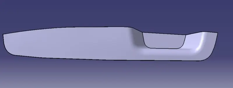
Week 8 - Challenge 2 - Switch Bezel Design
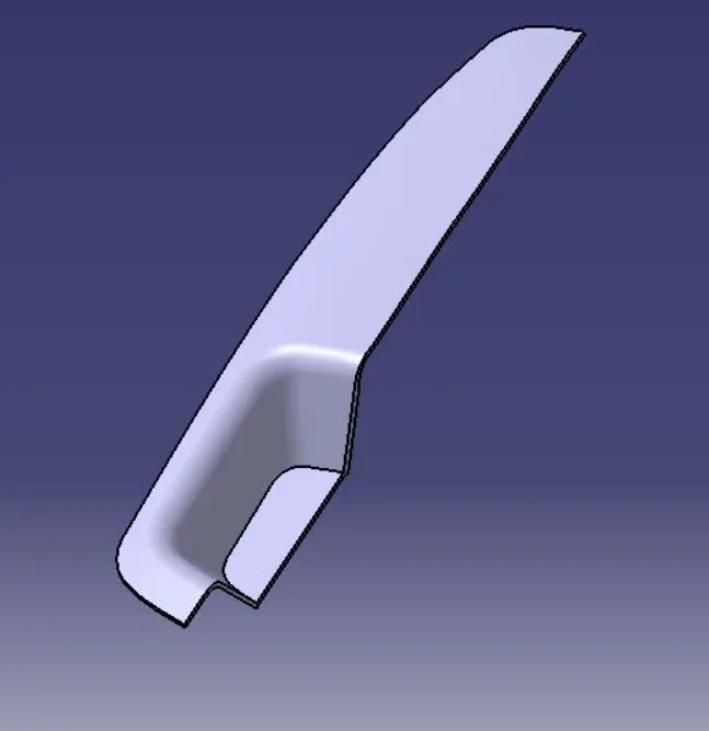
We have input as an class A Surface.
Step-1
- So our first task is check continuity of class A surface using boundary or join command.As there is no gap between components so it clear 1st step.
Step-2 TOOLING AXIS
- So after visualising can say that Z direction is best for tooling Axis.
- We took made a reference point on lower surface.
- And created a new Axis system.
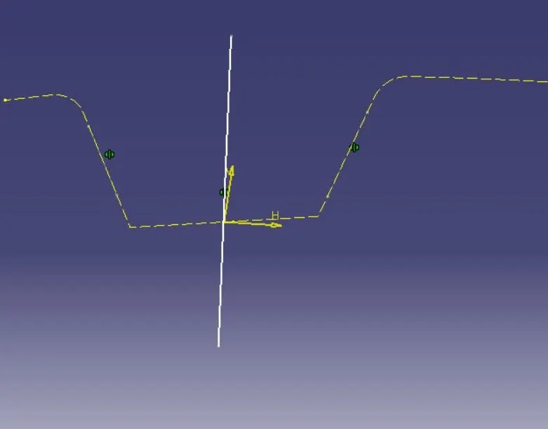
- Using positioned sketch on YZ plane, we used project 3D element ,project the wall faces on the y-z plane.
- Then two lines were created (as shown below image) and a new bisecting line were made using these 2 lines.
- So this bisecting line clear y direction.
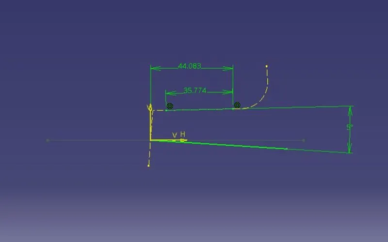
- Using positioned sketch in XZ direction, create a intersection and we create a line which coincide the wall (in z direction).
- Since there is no other wall ,we created a line on point in z direction and which angle 5° with the other line.
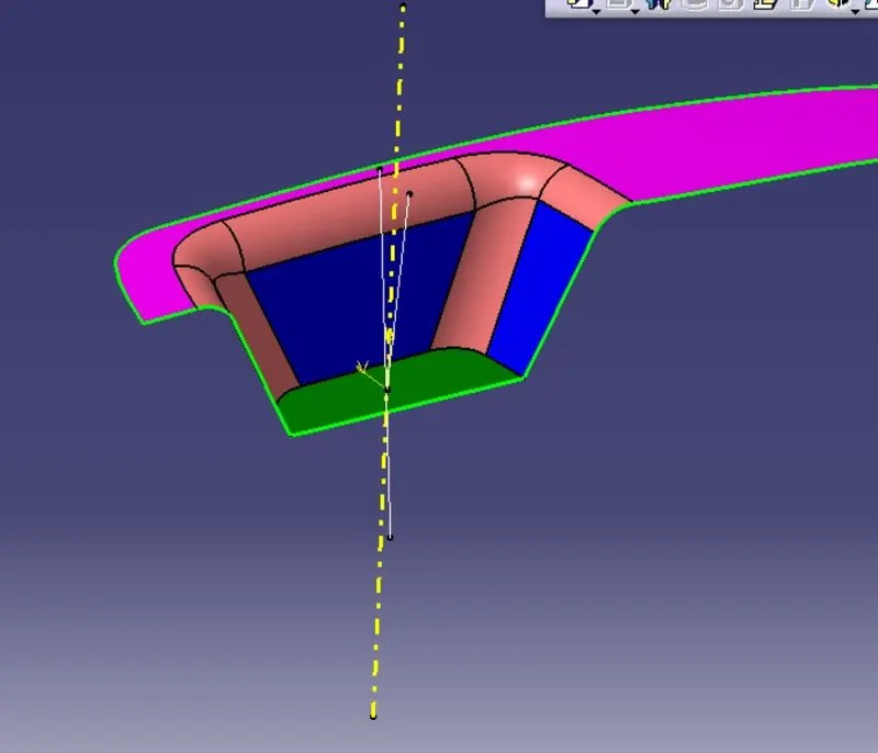
- Now bisect the this line with previous bisecting line(line that was clear y direction).
- So bisector of these 2 lines will be our tooling Axis.
For Y-direction
For X-Direction
TOOLING AXIS
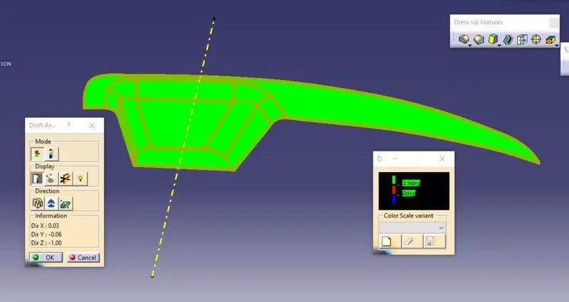
For draft analysis.
- For draft analysis go to
- Insert > Analysis > Features draft analysis
- (Make sure it should be in material mode)
- Now go to direction, and click 2nd option.
- Pick the compass and align it with the tooling Axis and click on the lock .
- Now click on the class A surface,we will see a green colour surface.
- Now give 2.9° draft.
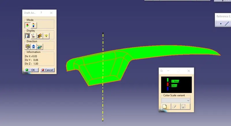
Draft analysis report for the final plastic component
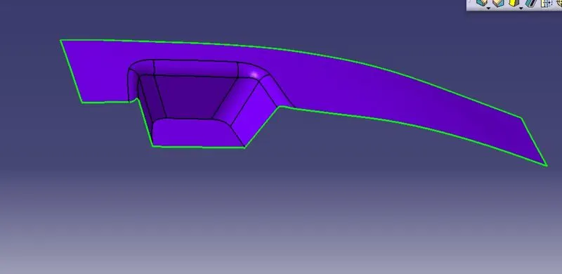
B-SURFACE
VIEWS