Week 8 - Challenge 3 - Coin Holder Design
Report
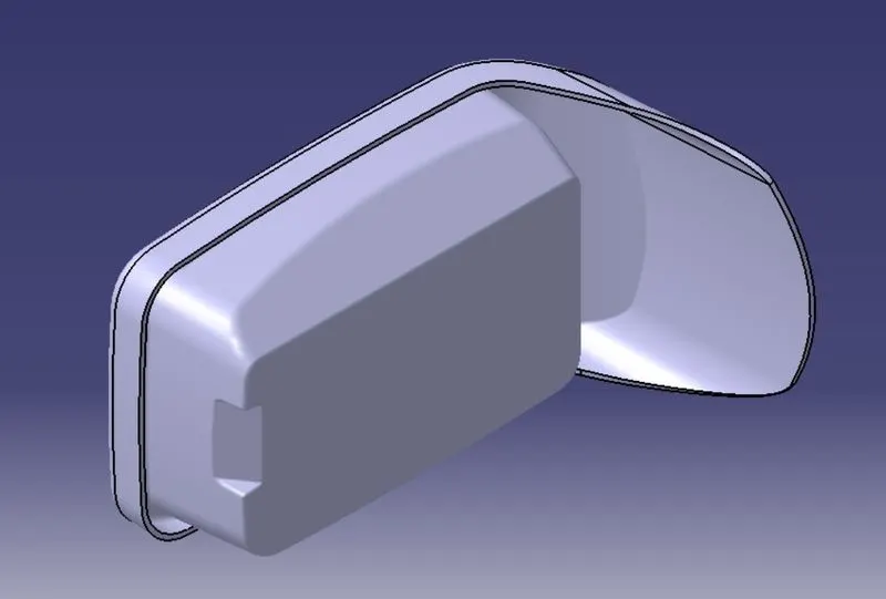
We have input as an class A Surface.
Step1-
So our first task is check continuity of class A surface using boundary or join command.As there is no gap between components so it clear 1st step.
STEP-2 TOOLING AXIS
After visualizing class A surface we can concude this
In X-direction and Z-direction it is not possible.
So, Y direction will be our tooling axis direction.
Creating tooling axis
- Extract base of class A surface
- Create a point on centre of extract.
- Create an Axis system, take origin as above point.
- Now intersect YZ plane with class A surface.
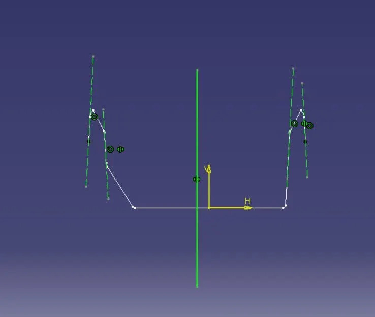
- Create A Positional Sketch, as we can see there are 4 lines which may cause problems.
- So now make bisector of these lines and final bisector Line will be clearing Z-direction.
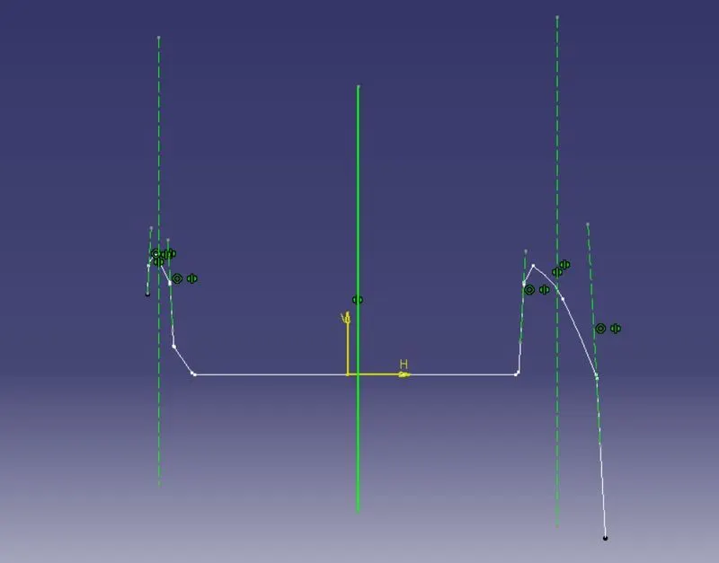
- Similarly intersect xy plane with class a surface
- Again create a positional scratch, as we can see there are 4 lines which may cause problem, so we will again make bisector of these line and the final bisecting line will be clearing z direction.
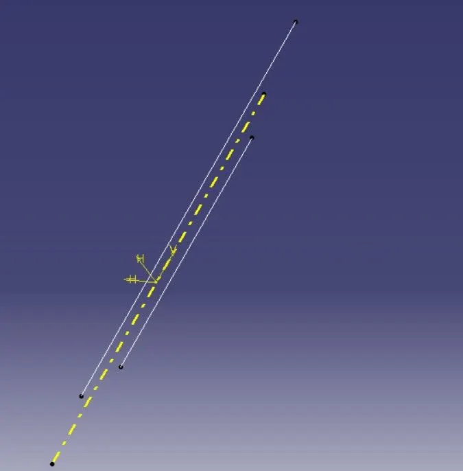
- Now bisect both these line.
- This line is our tooling Axis.
LINE CLEARING Z-DIRECTION
LINE CLEARING X-DIRECTION
TOOLING AXIS
Publish the tooling axis and class A surface.
For draft analysis for CLASS A -Surface
- For draft analysis go to
- Insert > Analysis > Features draft analysis
- (Make sure it should be in material mode)
- Now go to direction, and click 2nd option.
- Pick the compass and align it with the tooling Axis and click on the lock .
- Now click on the class A surface,we will see a green colour surface.
- Now give 3° draft.
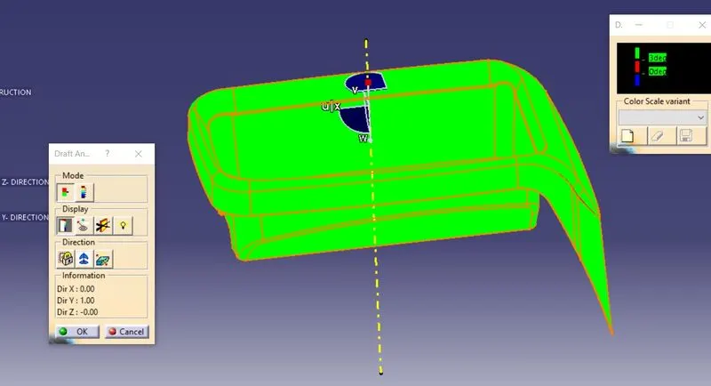
So basic draft analysis tool allow us to easily analyze the draft angle . It is very important to give draft angle because while ejection of parts/components in molding it will reduce friction with core and cavity and our part will easily ejected and will not damage . The draft angle nominal should be 3 degree. The green colour in above image of Class-A shows that it manufacturable.
Creation of B-SURFACE
- We will make SIDE WALLS at first.
- Extract the side walls and untrim them, after that extrapolate them
- Trim them and Offset 2.5mm
- Apply the fillets.
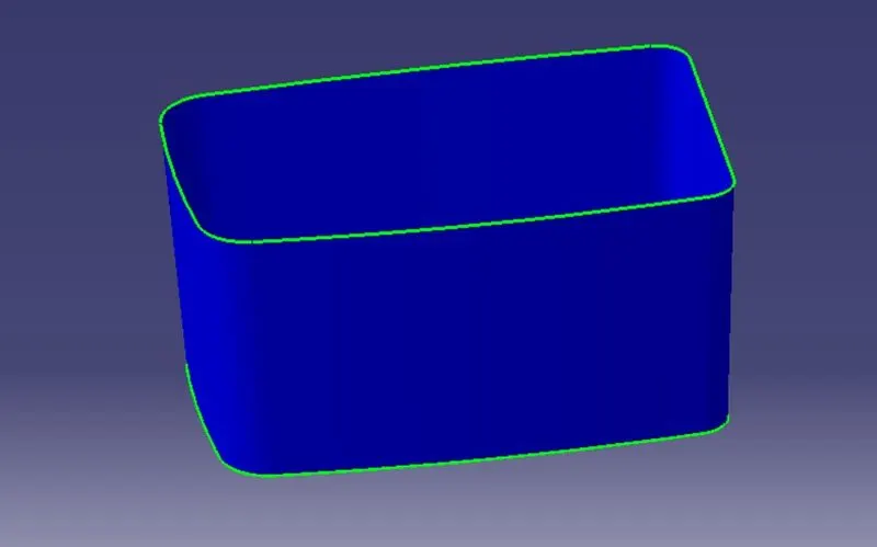
- Now for BASE, extract the base parts, untrim them and use extrapolate.
- Now trim the base parts together.
- Offset the the above trim.
- Now Trim side wall offsetwith above offset.
- Extract triangular parts and and untrim them and extrapolate
- Trim the triangular parts together, and Offset 2.5 mm
- Now trim the Triangular part offset with side wall with base offset.
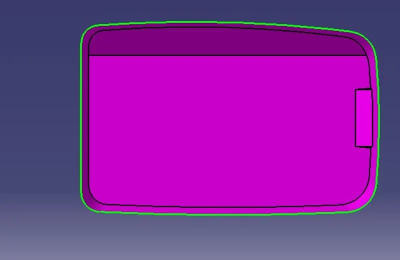
- Now for TOP WALLS use multiple extract to extract the walls and extrapolate both side.
- Offset 2.5mm.
- Trim above offset with previous Trim.
- Shown in below image.
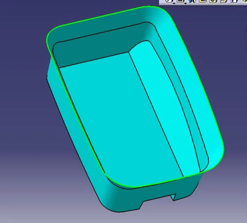
For outer parts
- Use multiple extract command to extract the outside part of class A surface and extrap0late it and offset it
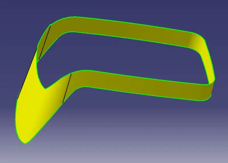
- Similarly use for other surfaces and extrapolate them
- join them and offset it
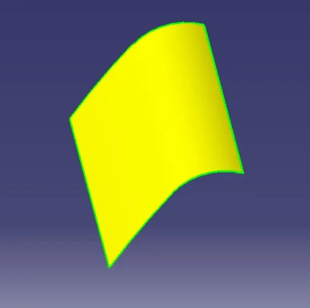
- The below image show trim of above three surface(Initial trim + above 2 offset)
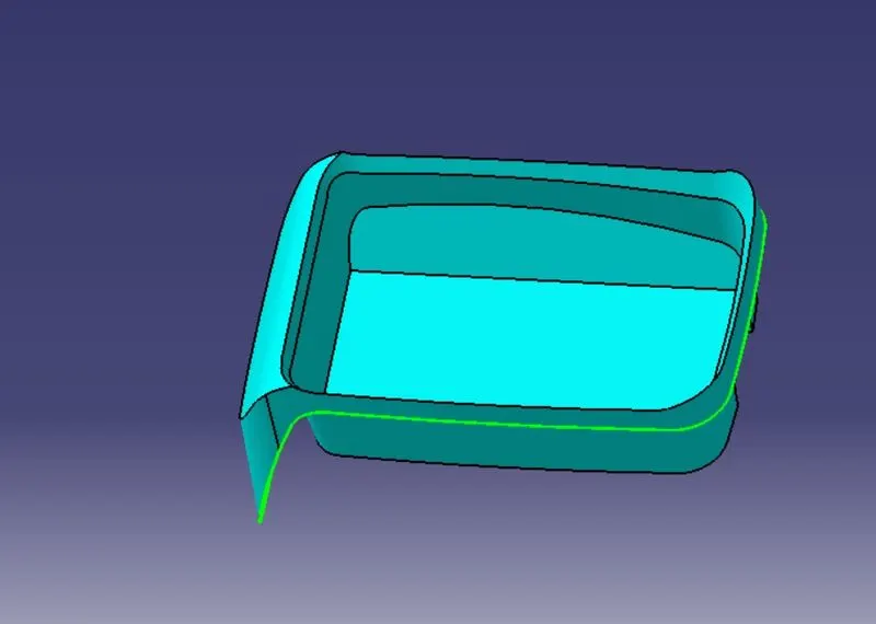
- Now apply fillets and B-surface is created ans published it.
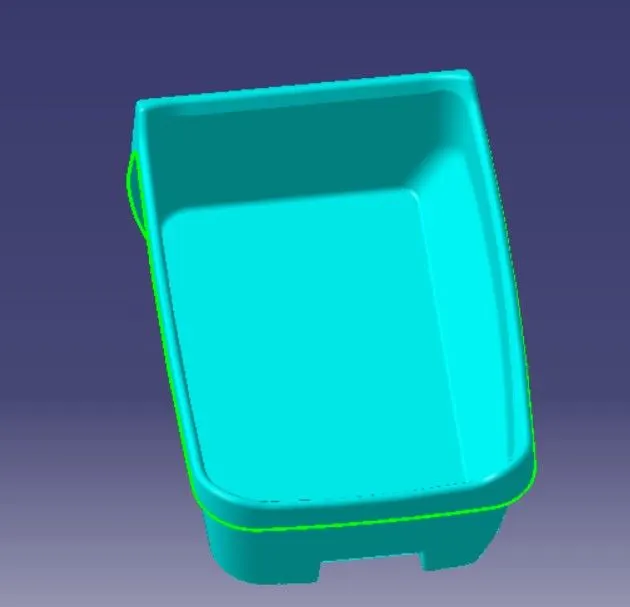
FOR C- SURFACE
- Used boundary command on class a surface.
- Extract outside wall of class a surface
- Now you sweep command.
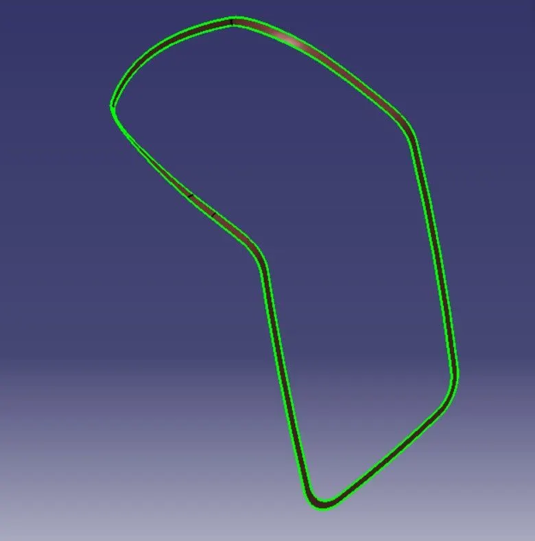
- Trim Class B with class C and join with class A
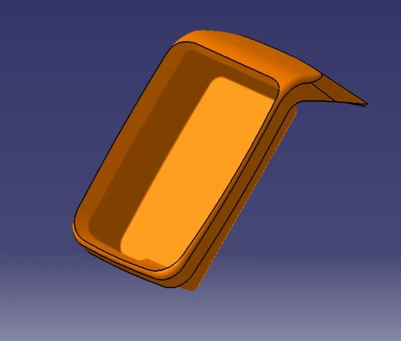
- Use boundary command to ensure our body is close.
- In part desgin workbench use close surface.
Draft analysis report for the final plastic component
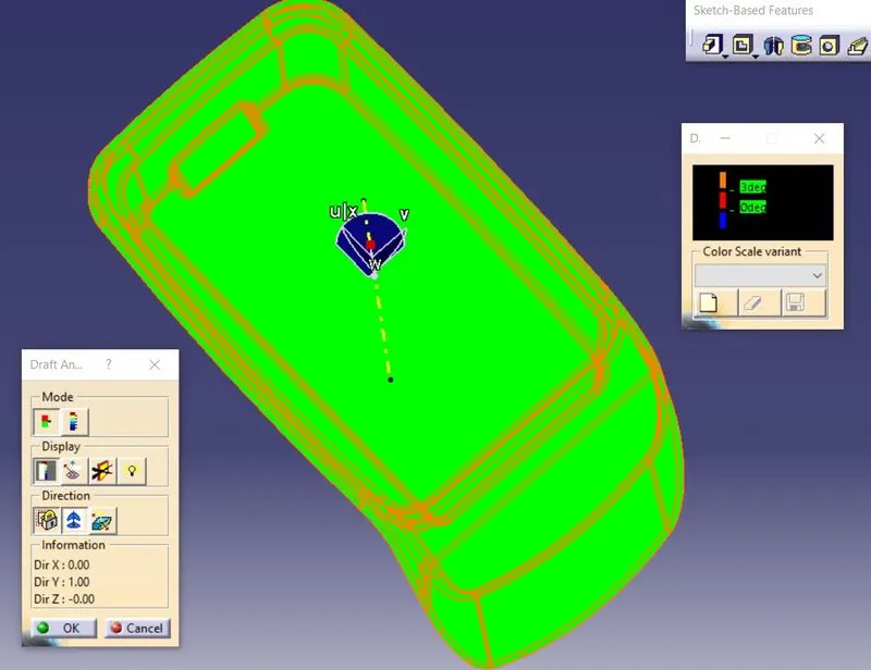
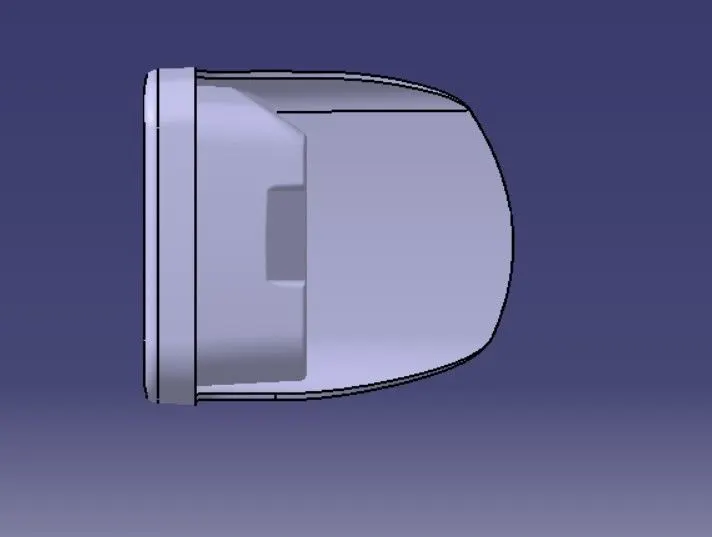
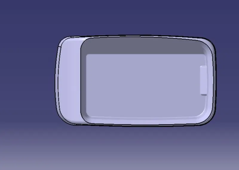
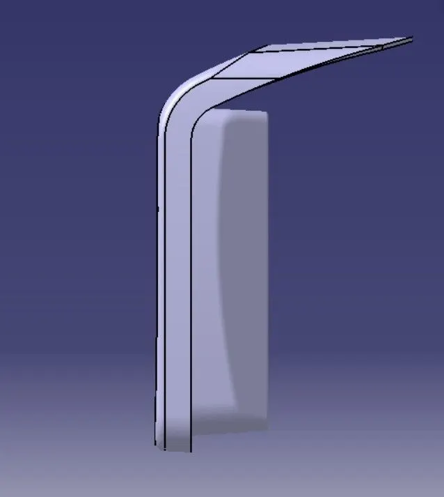
views