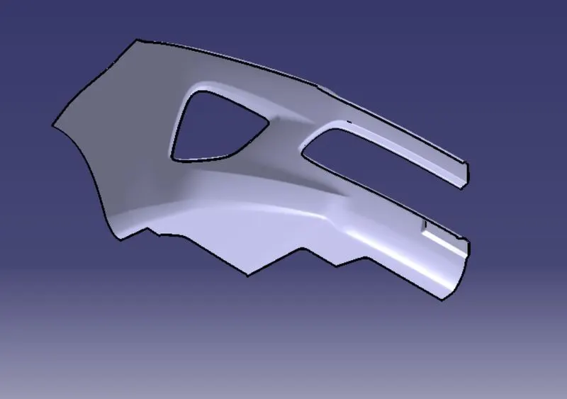
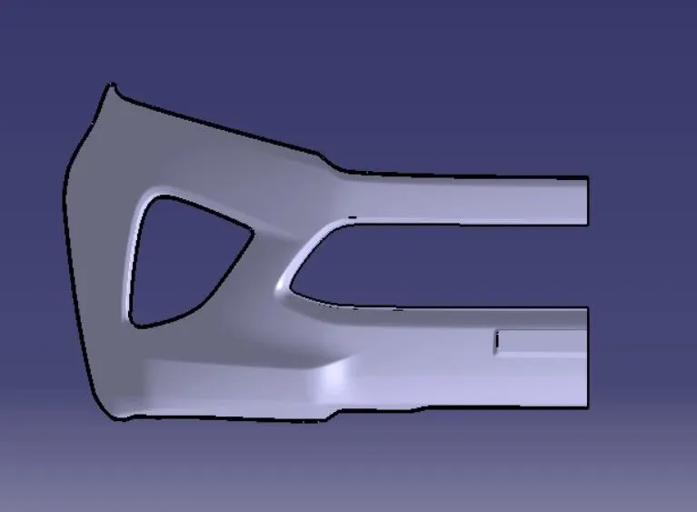
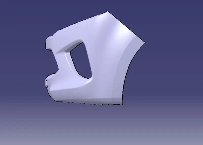
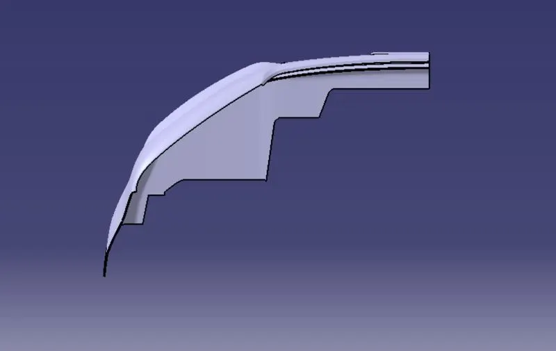
Week 8 - Challenge 4 - Bumper
Step 1-Our first task is check continuity of class A surface using boundary or join command.As there is no gap between components so it clear 1st step.
STEP 2 - TOOLING AXIS- After visualizing class A surface we can concude this
- X-direction will be our tooling direction.
Creating tooling axis
- Since Our bumper shape is complicated, so we cannot find tooling axis using bisector method, insteaded of that i have used hit and trial method
- When our bumper will be mirrir(complete bumper), so it best to take tooling axis in middle of complete bumper.
- So i we can choose tooling axis that face which are flat face or rectangular face
- I could have choosen rectangular face but when i lookwd at normal view from rectangular some corner fillets were not visible , so i choose other flat face(shown in below image)
- Extract the flat face and make a point a centre.
- Draw a line a line at point and take direction as x.
- This line is our tooling axis.
- Publish it
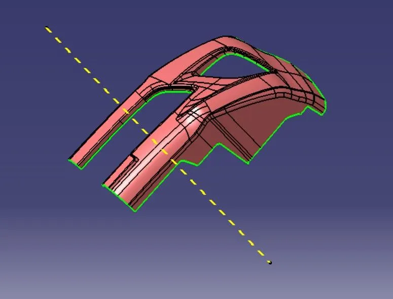
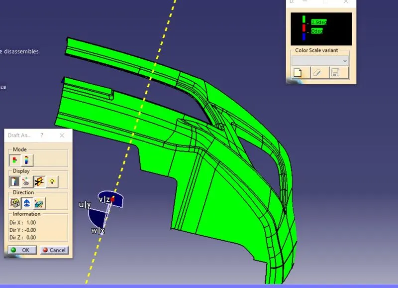
For draft analysis for CLASS A -Surface
- For draft analysis go to
- Insert > Analysis > Features draft analysis
- Make sure it should be in material mode
- Now go to direction, and click 2nd option.
- Pick the compass and align it with the tooling Axis and click on the lock .
- Now click on the class A surface,we will see a green colour surface.
- Now give 2.9° draft.
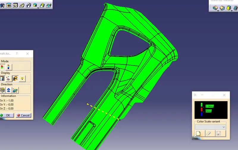
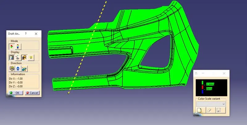
CREATING B-SURFACE
- Offset the class a 3mm.(below image)
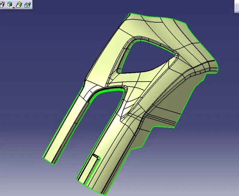
- we noticed there are some fillets which are missing
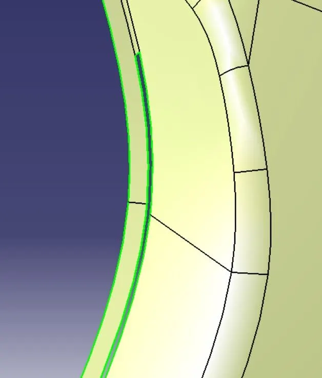
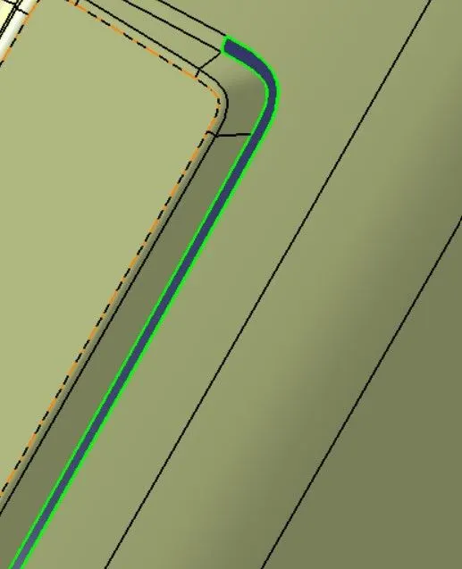
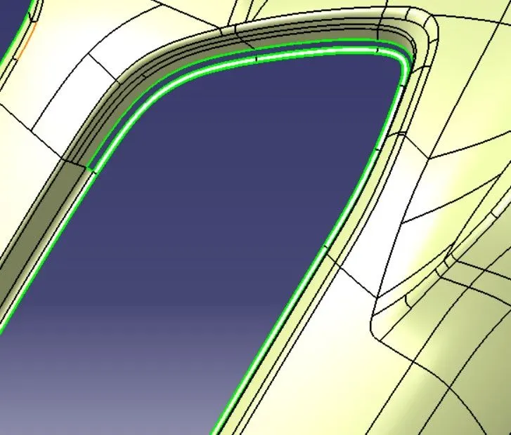
- We have to fill them
- We used multiple extract and selected the fillets which are incomplete and and also tick on Complementary mode.
- Now used disassemble operation.
- We will have 4 separate faces and i have given name as.
Image of main face
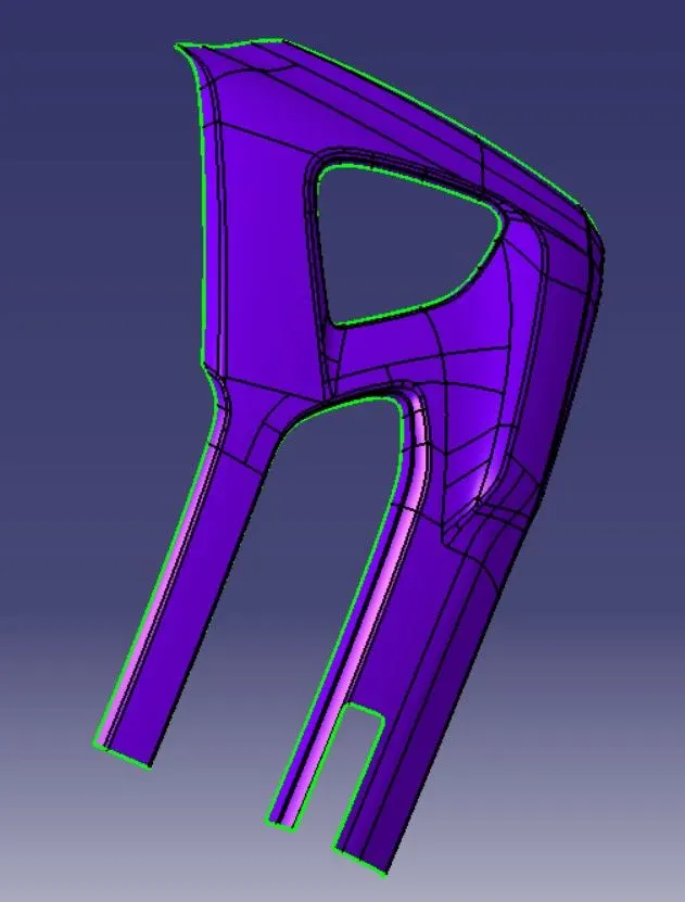
IMage of 1St FACE and Rectanglar face
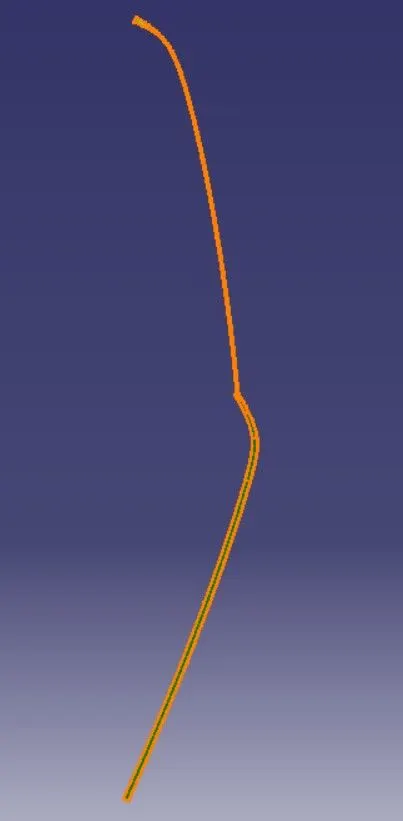
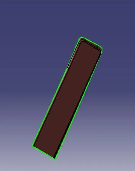
Image of Small middle part
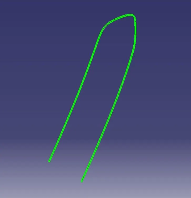
- So now will join these face with each other using extrapolate and trim operation
- Image of Main face trim with 1st face
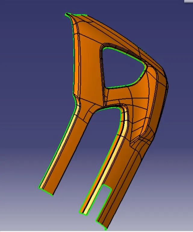
Image of 1st+miain trim face with rectangular face
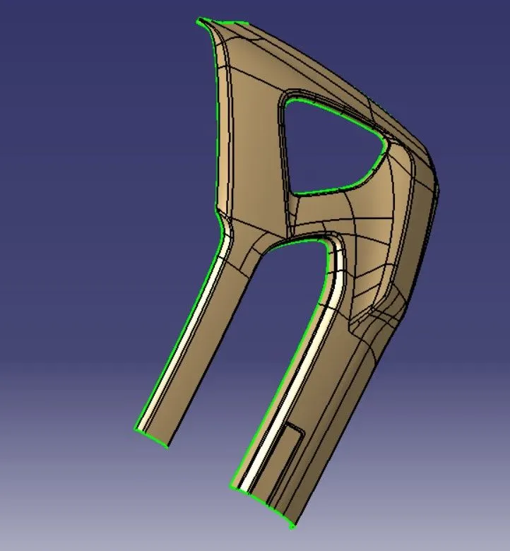
Image of 1st+miain + rectangular face trim with centre small part
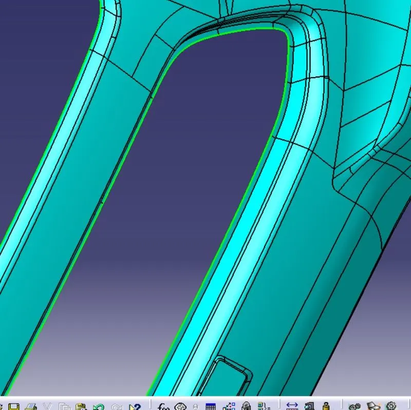
- Now apply the fillets and our B SURFACE is ready
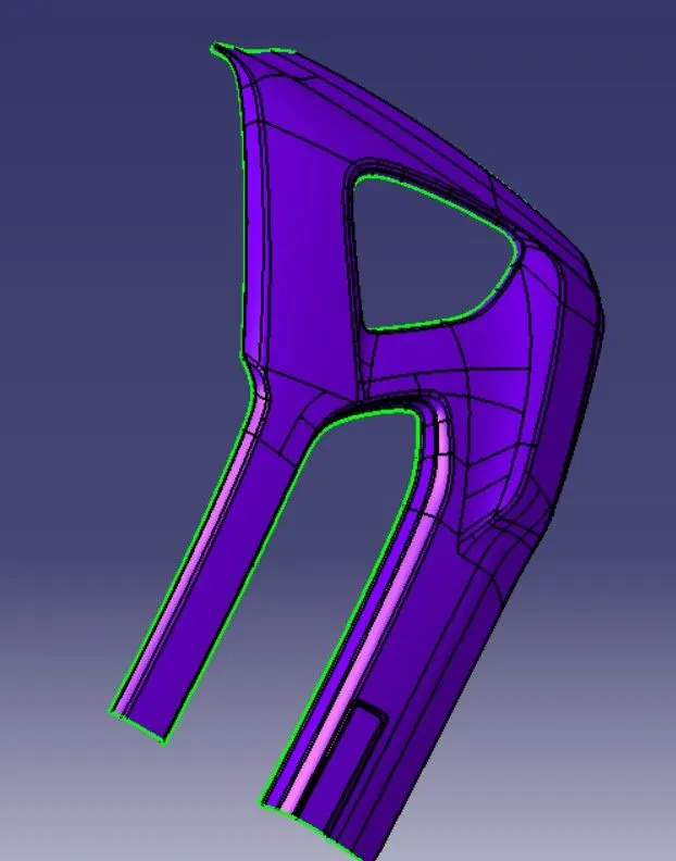
CREATING C-Surface
- Class C surface is use to connect A and B surface
- Since our shape is compilcated so we can created class C surface using single boundary.
- I have use mostly swept using reference surface
- The C-surface which is parallel to tooling axis ,i have used swept using draft direction.
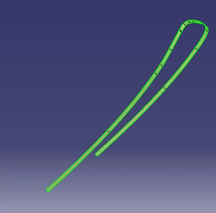
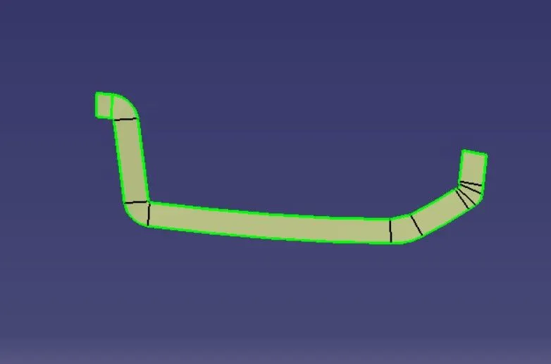
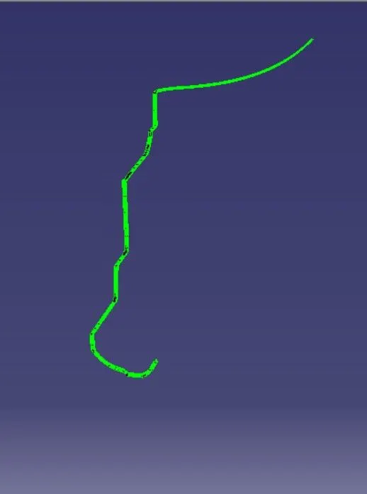
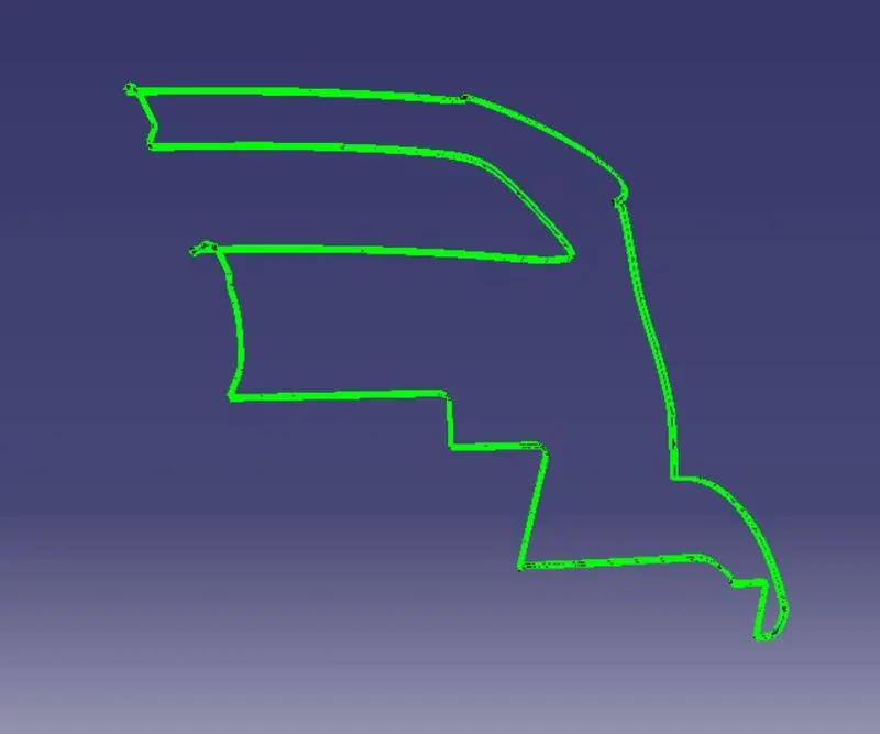
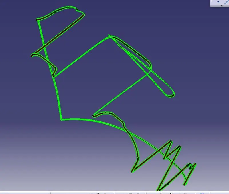
A+B Surface
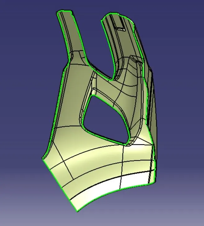
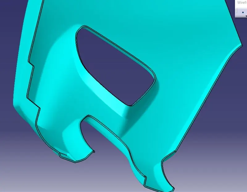
A+B+C
Draft analysis report for the final plastic component
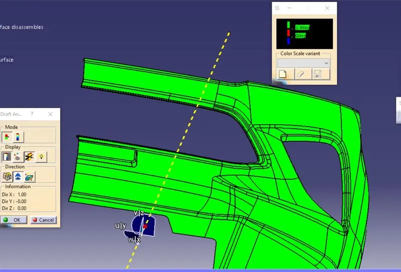
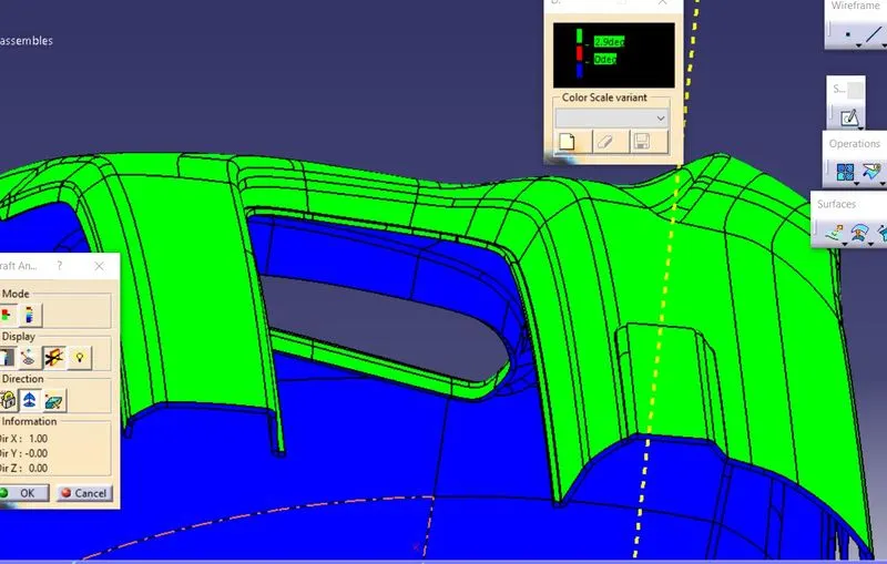
Views