Week 9 - Attachment Feature Creation - Challenge 2
Attachment Feature Creation - Challenge 2
Aim:
Create the Dog House for the Door Trim considering the design rules mentioned in the video.
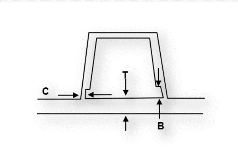
"C" is where the doghouse contacts the backside of the surface
- Doghouse wall thickness at the intersection of the part wall ( C ) should be 40% or less than the main wall stock ( T ).
- The height of ( B ) should be between 3.0 – 6.0 mm
Objectives:
- A detailed report should be done explaining the draft analysis and the tooling axis creation.
- An explanation should be given on the way of creating the tooling axis, particularly the Bisecting method.
REPORT:
Dog Houses:
Dog house: Dog house is an engineering feature used in the plastic trim design. Dog
houses are used as supporting features. Sometimes other engineering features like
snaps; locators, etc. are mounded on them to increase their strength. Dog house and
other engineering Features are built on B-surface.
TOOLING AXIS: The mold is built in two separate pieces, basically. You have a Cavity side and you have the Core side. The Core pulls apart from the Cavity and that's the Dyeline or the Tooling Direction. Again, depending upon where you're working at, you may have a different name for it. So, when you go in and you create that Tooling Direction, you want to make sure that whatever you create is going to be used as a reference to design your data up against. So, when you add in your ribs, maybe some pockets, walls, whatever that may be, bosses, the walls are going to be drafted based off of the Tooling Direction. It's to make sure that the Core can pull apart from the Cavity, nice and clean.
Creation of tooling axis.
- Tooling axis here created is by selecting one of the natural axes as it clears the draft.
- Here, tooling axis is created by extracting one of the surfaces for creating a point and a new axis is created at that point.
- So, a flat face is extracted and created a point at its centre. Axis is also created at that point.
- Now, line is created using line tool and giving line type as point-direction and selected the point and direction for creating tooling axis and tooling axis is created along z direction.
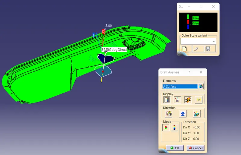
Draft Analysis of Class A surface
Draft analysis is performed over Class A surface and every surface is obtained as clearing.
Creation Of Class B Surface
- Now, Class B surface has to be created. For this, multiple extract is used to extract surface in a single operation. Surfaces obtained are the offsetted for 2.5mm.
The Unfilled areas have to be filled with multisection surface and join them together
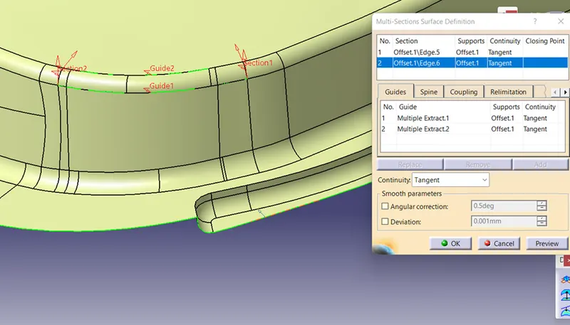
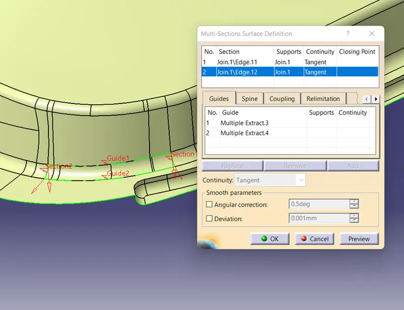
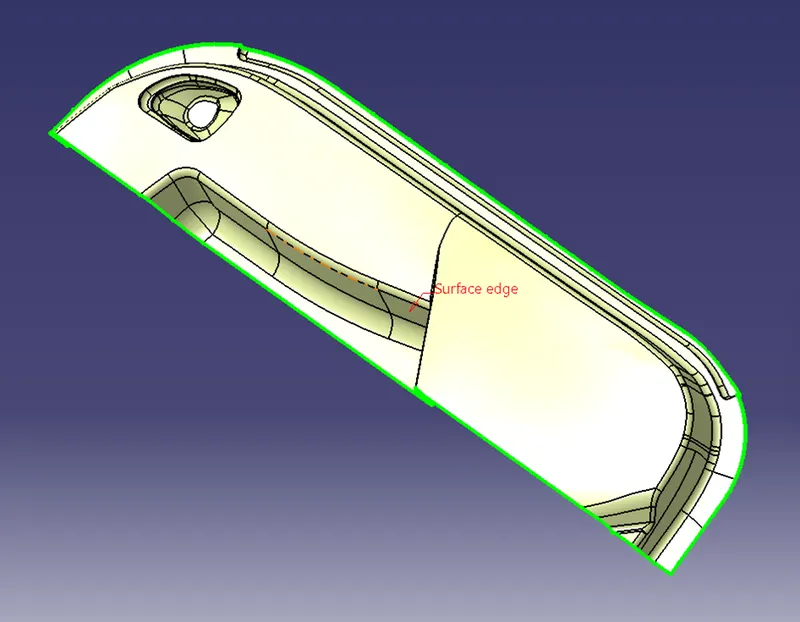
- Check the B surface by boundary command to make sure there is no gap in the surface.
Creation Of Class C Surface
- Now class C surface has to be created and it is created from the boundaries obtained from the Class A surface. This boundary is provided as the input curve for sweep command. Using sweep command, class C surface is created.
- Appropriate sweep is the provided considering the flash and considering manufacturing procedures. Surfaces are extrapolated if necessary.
- Publish class C surface.
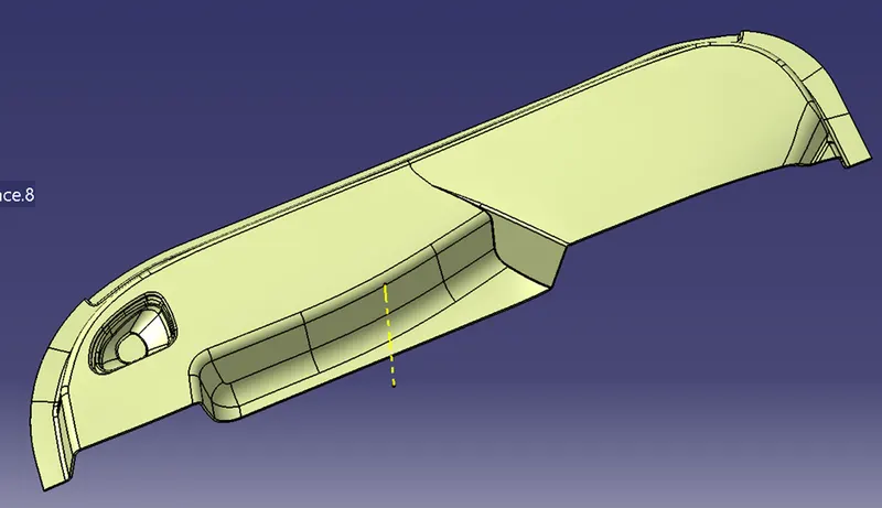
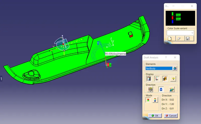
- Closed surface command is performed with the help of part workbench and later the draft analysis is performed.
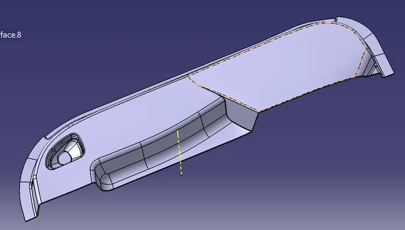
Dog House Creation
- Extract the face which is needed dog house and sketch on it. Create the profile for the dog house in the plane.
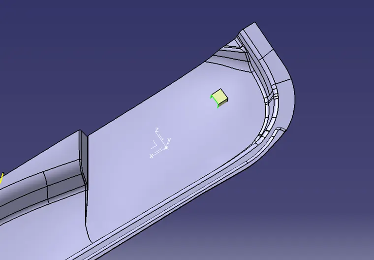
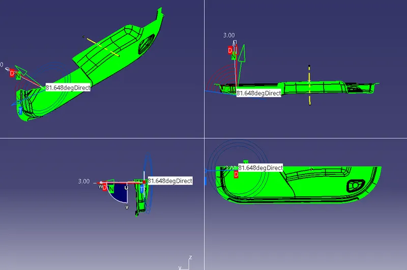
- Thick the surface for 2mm and give drafts for the sides wherever needed. Before that create side core axis for the draft analysis for the dog house.
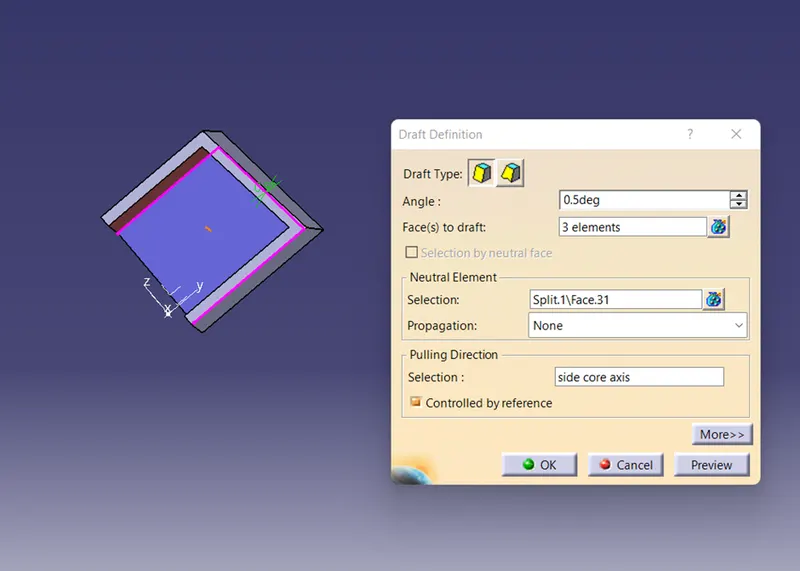
- Dog house intersection wall thickness must be 40 percentage or less than main wall thickness.
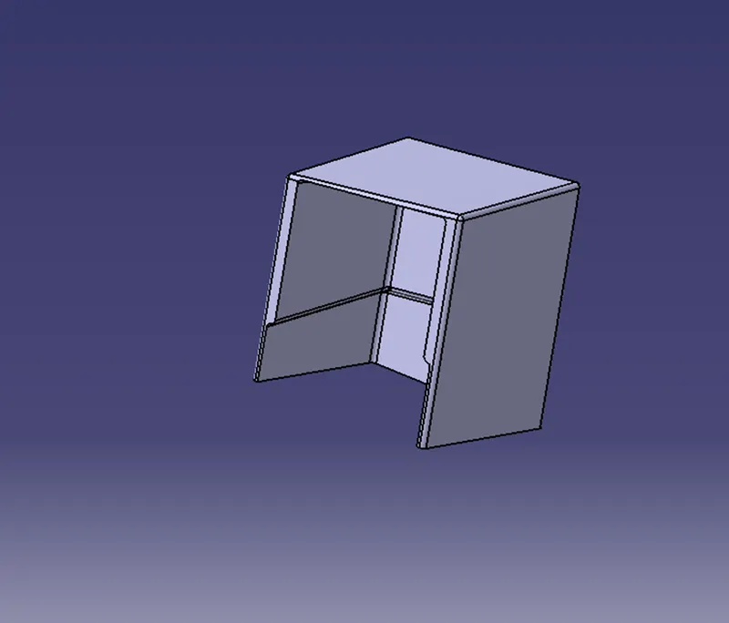
- Dog house added to the main part body by Boolean operation. And checked for draft analysis with the side core axis.
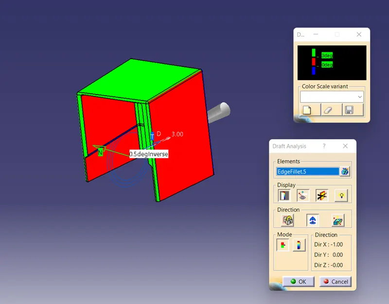
Closed Body
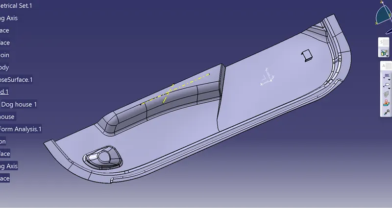
Draft Analysis Of the Closed Body