Week 9 - Attachment Feature Creation - Challenge 2
Part:-
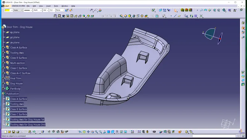
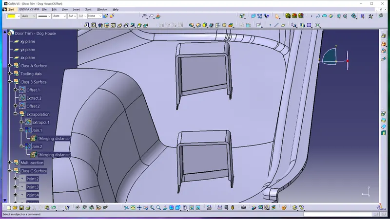
1.WALL THICKNESS:
Thick sections waste material and are simply uneconomic. So solid shapes that would do the job well in wood or metal must be transformed to a 'shell' form in plastics. This is done by hollowing out or 'coring' thick parts so you are left with a component which regardless of complexity is composed essentially of relatively thin walls joined by curves, angles, corners, ribs, steps and offsets. As far as possible, all these walls should be the same thickness. Wall thickness guide range is 0.75 mm to 3 mm for reinforced materials 0.5 mm to 5 mm for unreinforced materials.
Wall thickness = As material thisckness
Coaring wall Thickness = Guide range is 40% of material thisckness
2.DRAFT ANGLE:Tooling must be cleared for easy ejection of the component, from the core cavity. In order to clear tooling certain value of draft is given to the component. Minimum of 2-3deg is provides on all plastic components.
Minimum draft angle for the for all engineering features is 0.5 Degree (According to Skill-Lync data)Draft Analysis:-
The draft analysis technique is used to analyze whether our part model created in CAD is manufacturable based on the draft condition applied. Here the part should get easily removed from the panel dies (in case of Sheet metal part) or Mold (in case of plastic).
No parts can be ejected from the tool if it is having a straight 90-degree profile from its base surface. A small draft angle is provided to each and every area of the component in order to get easy removal of the component from the tool.
Here we are providing a direction in which components should eject in order to get easy removal of components from the tool. In other words, it also lets us know whether the model is having a draft angle and how much is the draft angle from the tool direction.
Minimum draft angle for the for all engineering features is 0.5 Degree (According to Skill-Lync data)