Week 9 - Attachment Feature Creation - Challenge 2
Week 9 - Attachment Feature Creation - Challenge 2
AIM
Create the Dog House for the Door Trim considering the design rules mentioned in the video.
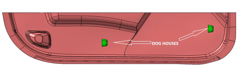
Requirement
- Screenshots of the completed design in various orientations (Isometric, Front, Side, and Top View)
- A detailed report should be done explaining the draft analysis and the tooling axis creation.
- An explanation should be given on the way of creating the tooling axis, particularly the Bisecting method
- CATpart should be submitted as an attachment
REPORT
Dog House
Main use of Dog House is to avoid sink marks and install engineering features snaps, locators etc. on it. It also used to give support to long screw boss to reduce their height. And to fit screw bosses in the direction other than tooling axis.
Tooling Axis
Tooling axis is a direction in which core and cavity opens and closes. Draft angle is provided with respect to the tooling axis. While creating mold component from Class-A surface, we need to decide the tooling direction. It can be decided by visual inspection, deciding complex surfaces and bisecting method.
Tooling Axis Creation- Bisecting Method
- First check for the discontinuity of the surface received by join or boundary command. Then visual observation is done to decide which direction will be more feasible to create component.
- Few surfaces are identified which can create concern over draft angle
- A reference point is created in center of the bottom surface. And Axis system is created at that point.
- Two different cross section profiles are formed using intersection with plane.
- For first profile in xy plane, Lines are drawn on the concerned boundary intersection profile. Then line is drawn bisectiong these two lines.
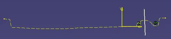
- For the second intersection profile in xy plane same procedure is followed.
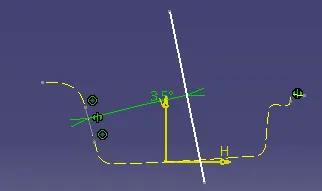
- A bisecting line is created from the two lines created earlier with intersection profile. This bisecting line refered as Tooling axis line and this method is known as Bisecting method to create tooling axis.
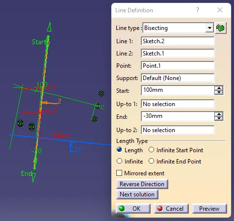
Draft Analysis
To reduce the risk of damage to parts and tool while ejecting from mold a draft angle is provided to walls which are parallel to the tooling direction. It assists with releasing the part from mold.
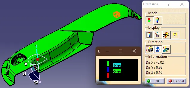
To perform Draft analysis in Catia, Draft analysis feature is used. For that First tooling Direction decided. Then make sure material view mode is used. After opening the window, align the compass with the tooling axis by dragging it on the axis. Then click on the surface or the body on which draft analysis is need to perform. In the bottom black colour window provide the minimum draft angle and then match the body color with this color scale. Green indicated draft angle is more than minimum draft angle. If it is blue then it is between 0 to minimum draft angle. And red denotes it is less than zero. By this way we can identify the areas with draft angle less than minimum draft angle and work on that area by changing tooling axis angle.
Procedure
- Check for Discontinuity. If any, join the surface. And Publish it as CLASS A surface
- Identify concern planes. Create line in every concern planes. From the these line create bisecting line ie. final Tooling axis.
- Perform Draft analysis on Class A surface in the Tooling Direction
- Create Class B surface by offseting Class A surface and join them by trimming. Fillet Edges. Or use fill by creating close profile.
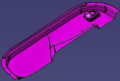
- Create Class C surface by extracting boundary of class A surface and sweep it by minimum draft angle along the tooling direction.
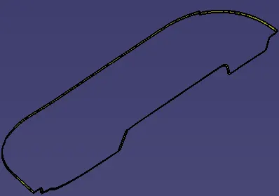
- To create final closed surface body, join and trim all three surface together and finish by giving remaining fillets.
- Convert this surface body into Solid body by Close Surface Tool
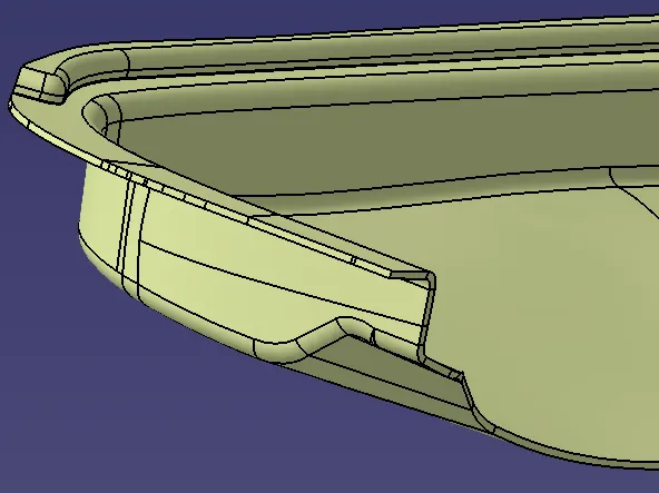
- Create skech for outer walls of Dog house and sweep it in tooling axis directin with draft angle. Create side tooling axis for inner draft. Give fillets, thickness and add it to the main body.
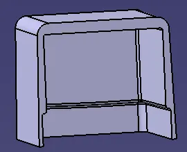
- Perform Draft analysis again on the Solid body.
OUTPUT
DRAFT ANALYSIS
In the 1st image, minimum draft angle is kept 3 degrees for the main body in the main tooling axis. Most of the surface has draft angle more than 3 degrees.
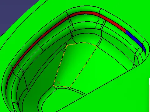
At some faces draft less than 3 degree or negative, for such places Draft angle of Class A surface need to be change. This suggestion is provided to the styling team and get their approval.
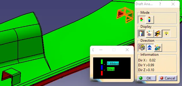
In the 2nd image, draft anlysis is performed for outer wall of dog houses with respest to main tooling axis. The minimum draft angle is 1.5 degrees. And it passes the test.
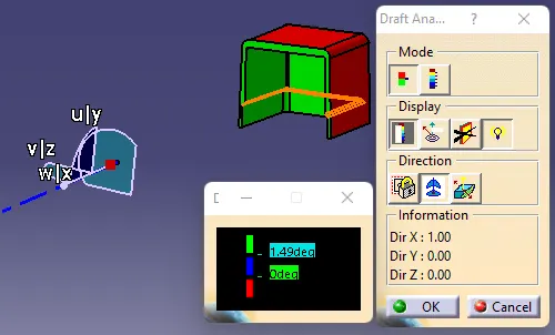
In this image draft analysis performed on inner walls of dog house in side tooling axis. Minimum draft angle 1.5 degrees and it passes the test.
3D Model Views
|
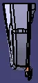
FRONT
|
SIDE
|
|
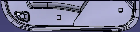
TOP
|
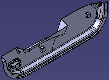
ISOMETRIC
|

CONCLUSION
Class A surface of Door Trim is successfully converted into solid body. And Dog houses are created on Class B surface and draft analysis is performed on it.