Week 9 - Attachment Feature Creation - Challenge 2
Hi fellows,
I am sending you required COIN HOLDER features and analysis as follows.
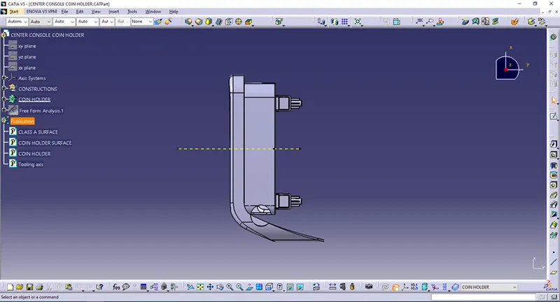
I have opened the CENTER CONSOLE COIN HOLDER and there was a Part as shown bellow.Then I have unhiden Tooling Axis and hiden Draft Analysis.
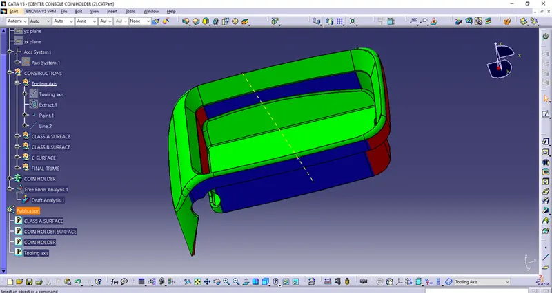
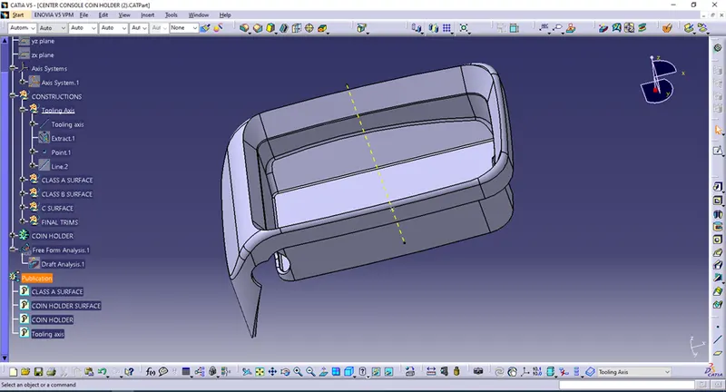
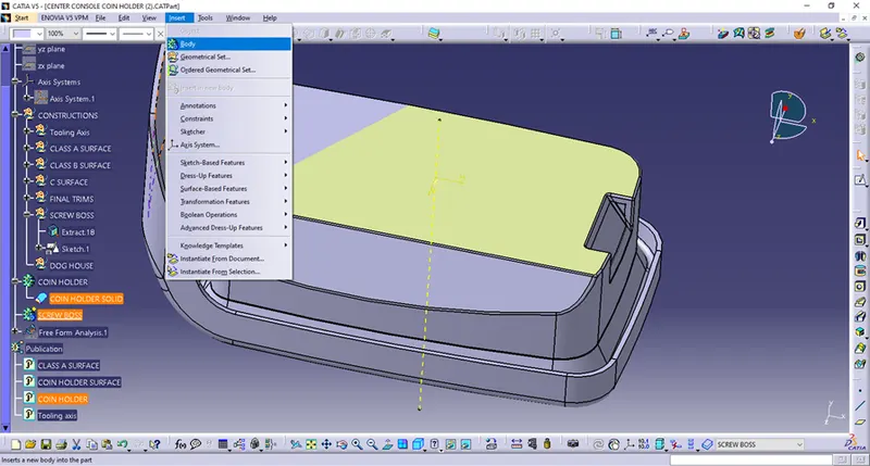
Then under Geometrical Set CONSTRUCTIONS I have inserted Geometrical Sets SCREW BOSS and DOG HOUSE.
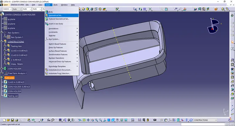
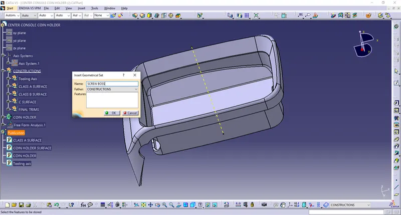
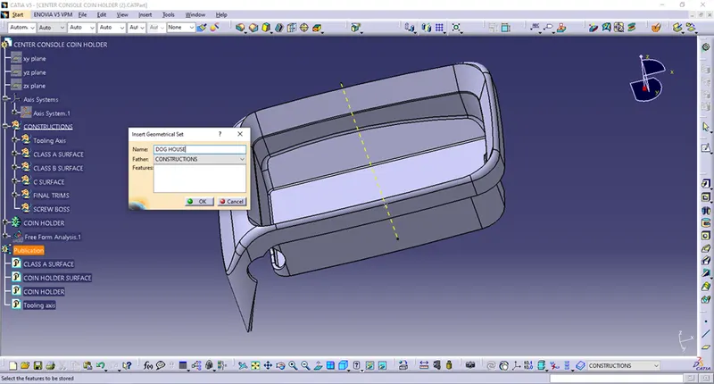
SCREW BOSS
Now on CLASS B SURFACE of bottom surface of the part I am doing extract surface as a reference surface for SCREW BOSS and DOG HOUSE.
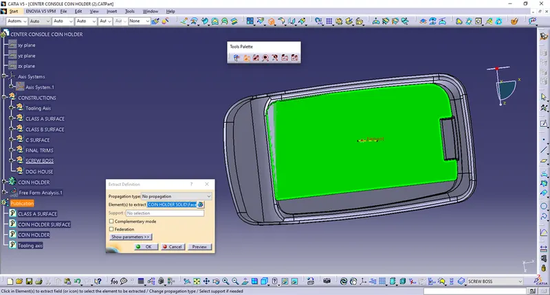
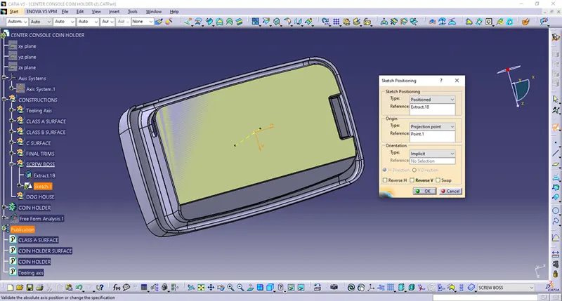
On the extracted surface I have done Positioned Sketch as shown bellow.I have presumed that I will be dealing with a M6 Screw,therefore I have done inner circle with diameter 5.2mm and there is a rule for a outer diameter or thickness of the SCREW BOSS side wall – it has a value 0.6 x Part thickness – 0.6 x 2.5mm = 1.5mm,therefore I have offseted inner circle for a 1.5mm and outer diameter is accordingly 8.2mm.
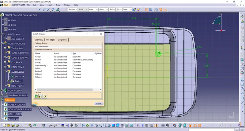
I am inserting New Body Part – I am renaming it as a SCREW BOSS where I will thicken those extrudes.SCREW BOSS thickness is 40% of the Part thickness (2.5mm) and therefore SCREW BOSS thickness is 1mm.
I have done pad with a Tooling Axis as a direction for pad.As I have outer diameter 8.2mm and Height/Diameter ratio is 2:1 till 3:1 and height of the Screw Boss is then 15mm.
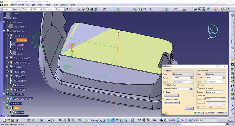
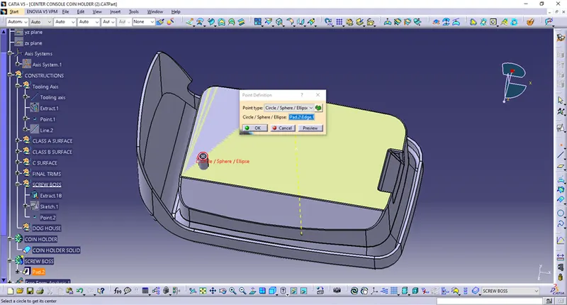
I need reinforcement for that SCREW BOSS cilinder and I am addin 4 ribs in it.In a Geometrical Set SCREW BOSS I am inserting point as a cricle center and that point and extracted surface are references for ribs. Here I will make Positioned Sketch for ribs as follows.
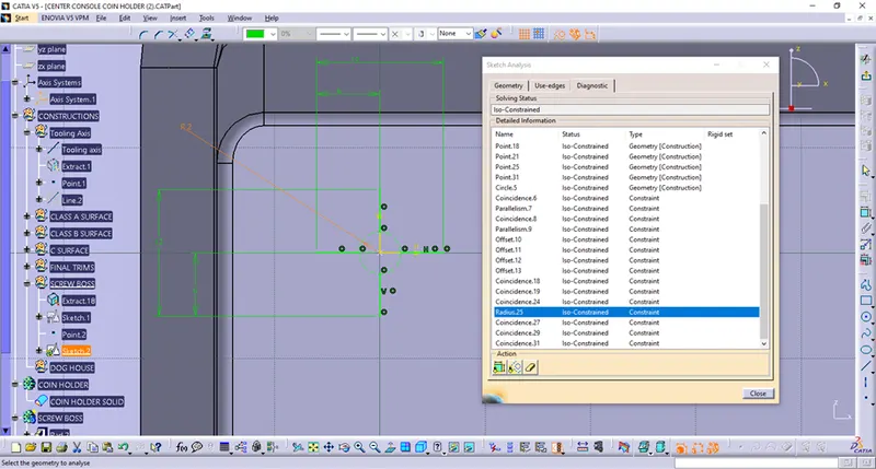
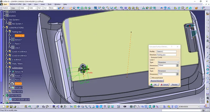
I am extruding that Sketch as follows (I am extruding it for a 12mm,it should be smaller than Screw boss height.When it has same height (Rib and top of Screw boss) than I will not have a plane surface on top, Fitting of adhesion surfaces will not be ensured,that is why Rib has a little bit smaller value.
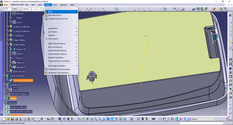
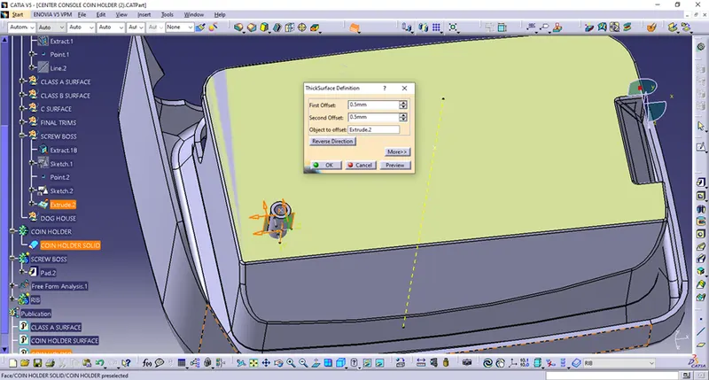
I am inserting New Body Part and renaming it as a RIB,where I will thicken those surfaces.RIB thickness is 0.4 x Part thickness,that means 0.4 x 2.5mm = 1mm.
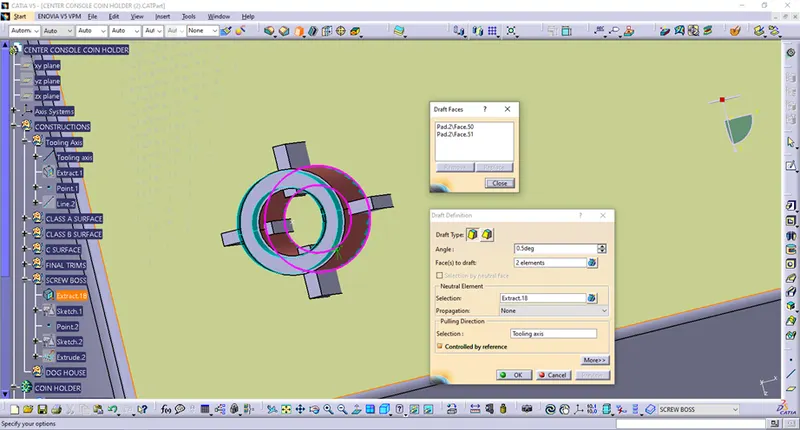
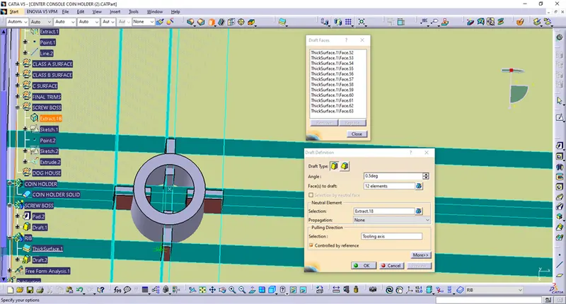
Now I am drafting those surfaces – Draft is 0.5 deg and reference suface – bottom surface extract and pulling direction is Tooling Axis.
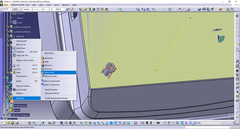
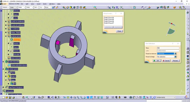
Now I am doing Union Trim of RIB and SCREW BOSS as follows.
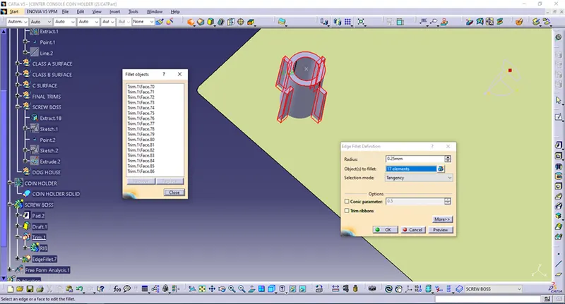
Then I am filleting SCREW BOSS feature – radius is 0.25mm.
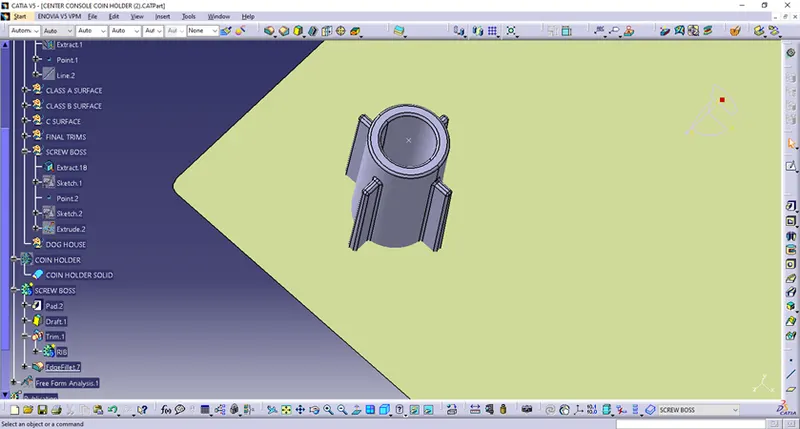
Then I have translated that SCREW BOSS features as shown bellow.In Geometrical Set SCREW BOSS I have drawn Position sketch with points of insertion SCREW BOSS features.
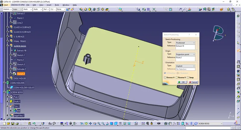
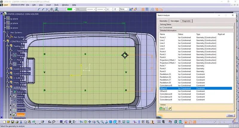
I am going to translate SCREW BOSS features in following points.First I am going to Copy-Paste with Link SCREW BOSS and translate it.
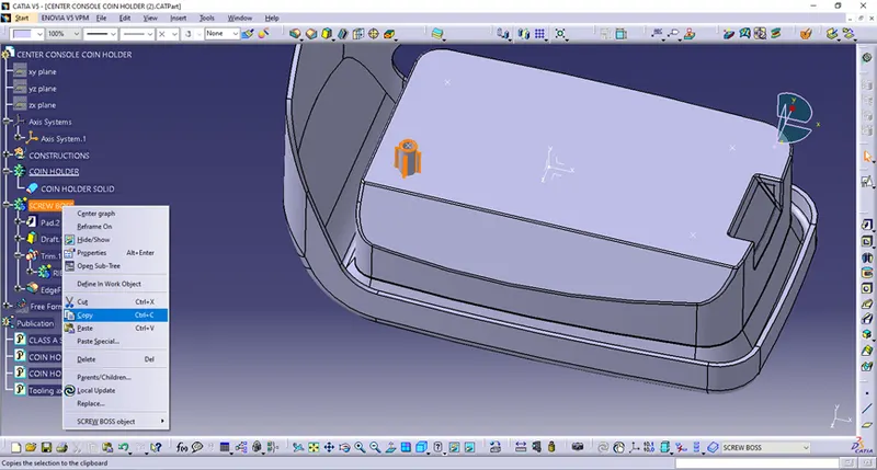

Pasted features are then translated.
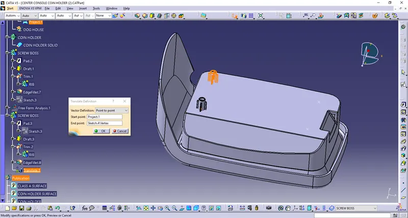
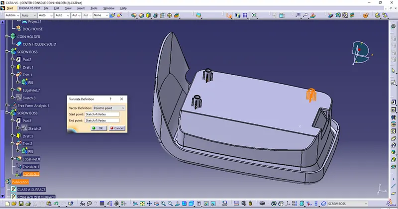
Then again Copy – Paste procedure.
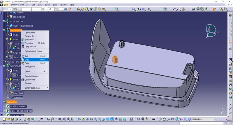
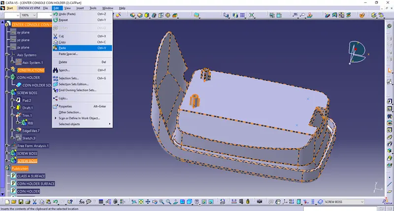
Then follows features translate.
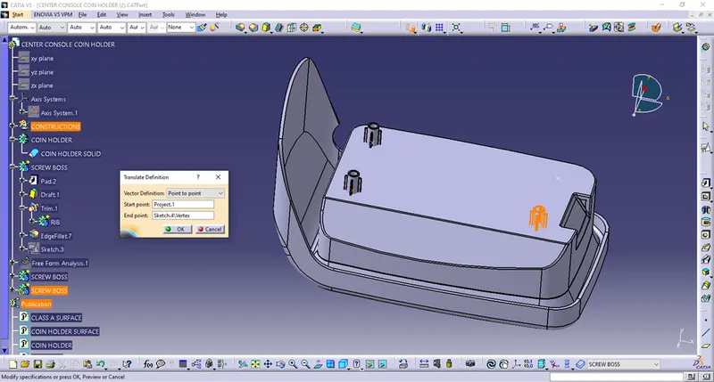
Now Copy – Paste procedure goes once again.
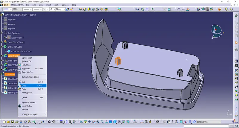
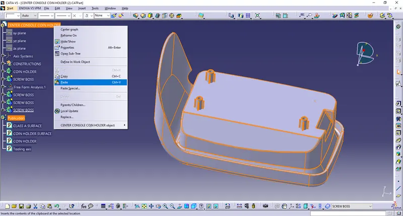
And then translate procedure once again.
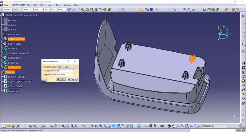
I have now added those features to CENTER CONSOLE COIN HOLDER feature and filleted them.
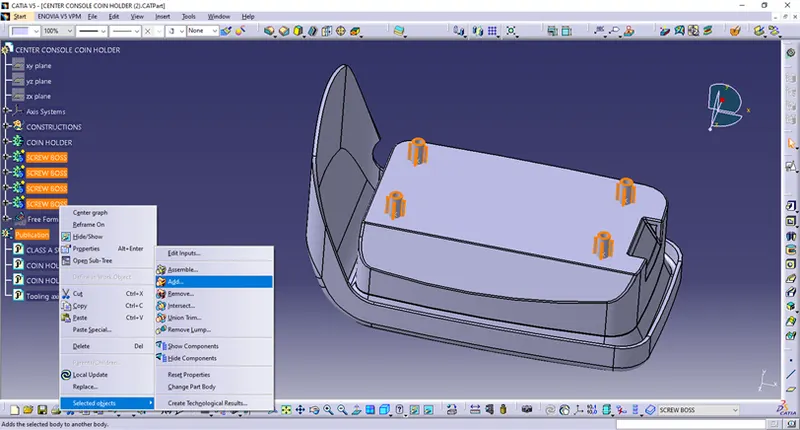
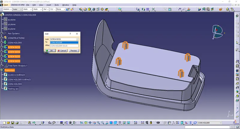
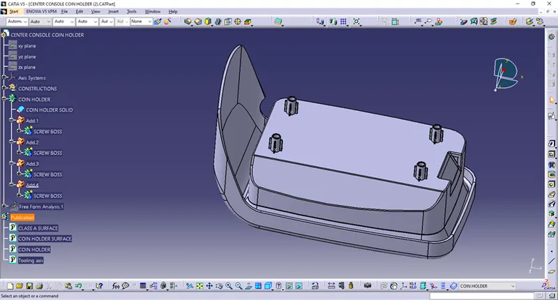
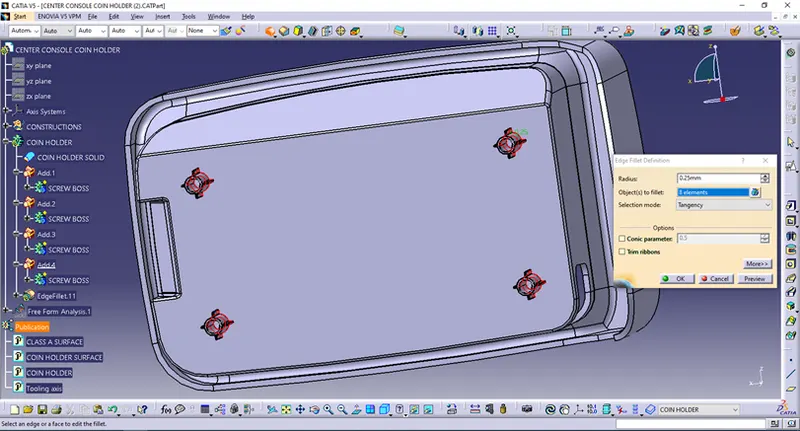
SCREW RIBs are filleted.
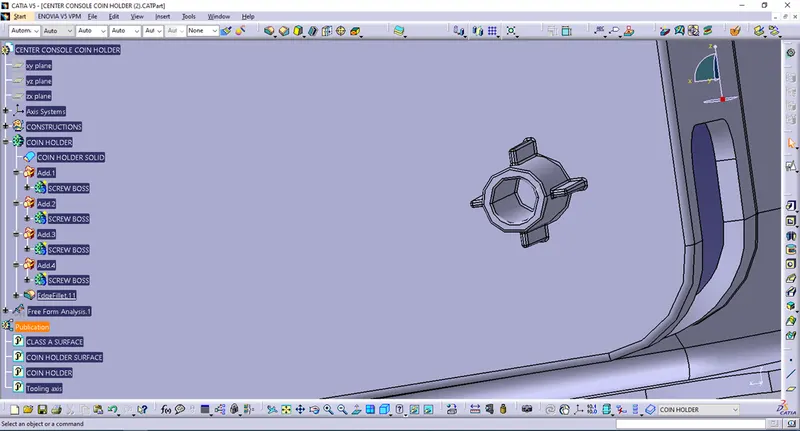
DOG HOUSE
Now I am going to deal with Dog House Feature.Sometimes there are various requirements on design either because of design requirements or space and instalation possibilities.Dog House is always designed in connection with Screw Boss to avoid to much thickness of the Part (Sink marks,flow lines,vacuum/air bubles etc.).There are also some rules in designing Dog House as by Ribs and Screw bosses and those rules will be applied and shown here.
So,under the Geometrical Set DOG HOUSE I am going to draw Positioned Sketch as follows.
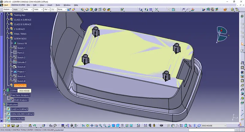
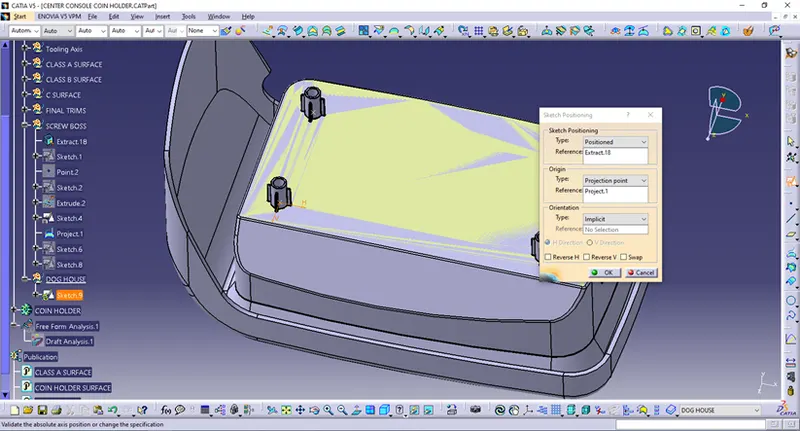
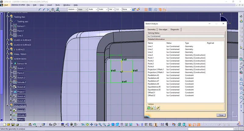
One side of Dog House should be open,to be able to mould the part and extract it afterwards.
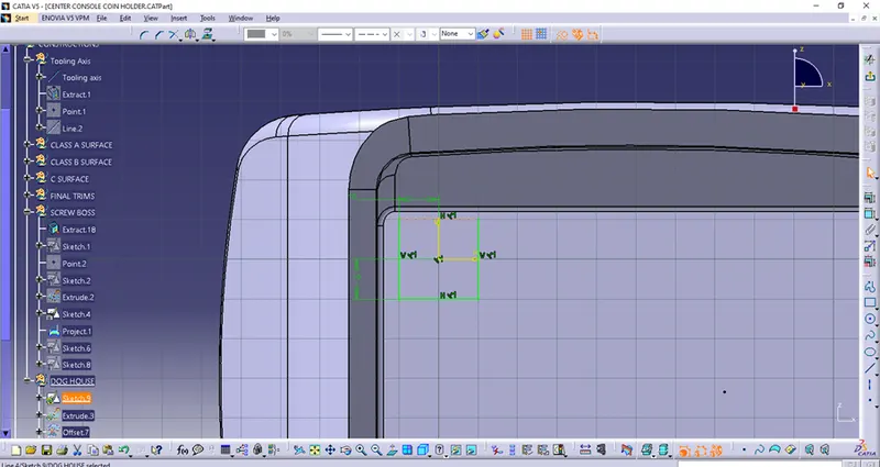
Then I have extrude the sketch.
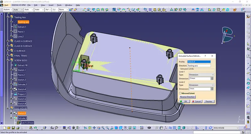
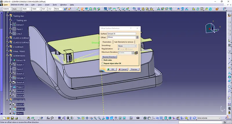
And offseted a extract for a 20mm.
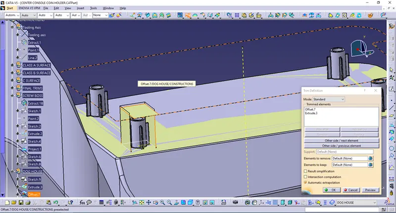
Then I have trimed it.
Afterwards I have inserted New Body Part and renamed it as a DOG HOUSE where I will thicken those surfaces.
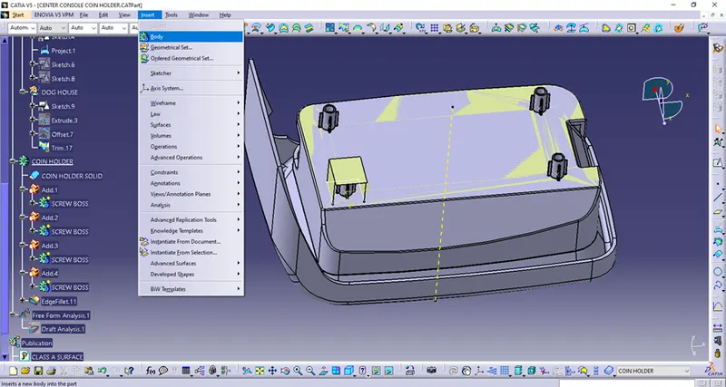
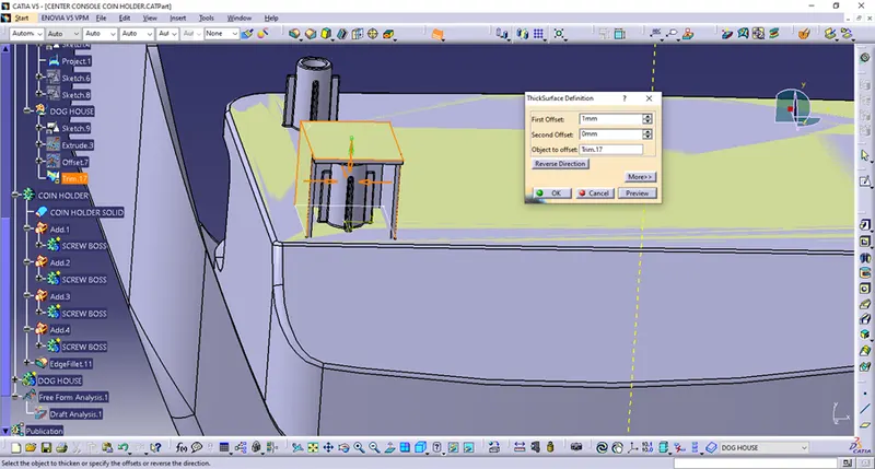
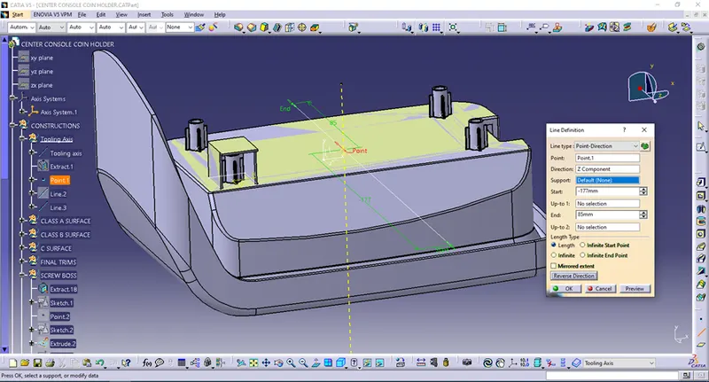
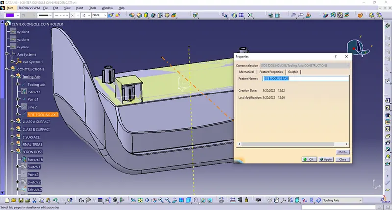
As it can be seen,for a so constructed Features,I need one more tooling axis to be able to extrude the Part from the mould.That tooling axis I will rename as SIDE TOOLING AXIS and change its graphic properties.
Now I am going to design&make changes of DOG HOUSE Body Part.First I am going to draw a plane regarding side wall.
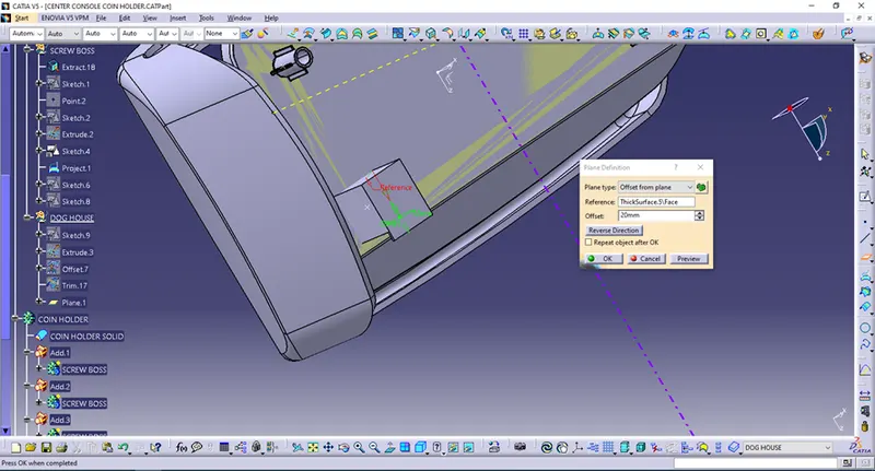
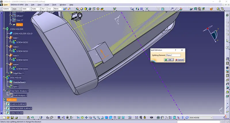
With that plane I have splited DOG HOUSE.
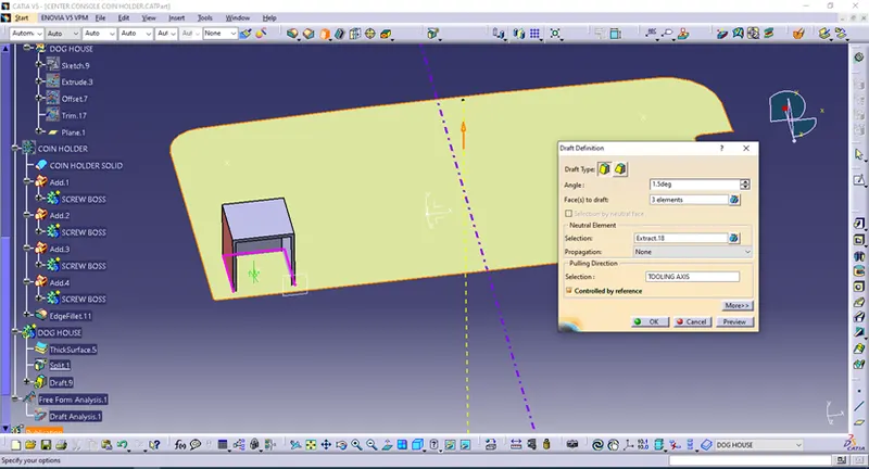
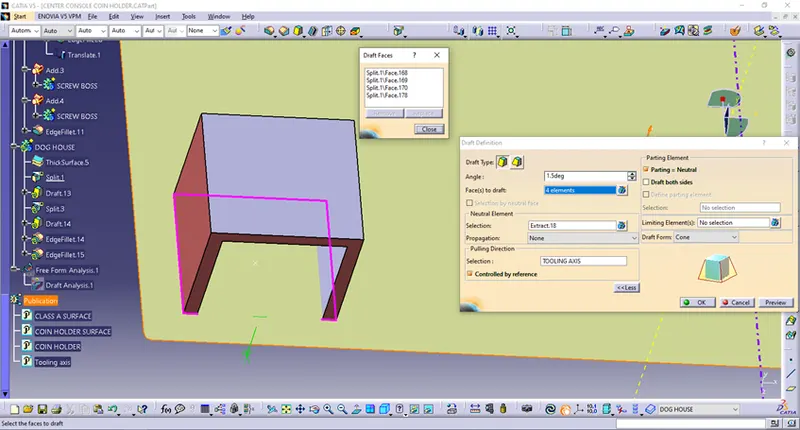
Then I have made a Drafts on the feature – minimum Draft angle is 1.5deg.
After Draft with main TOOLING AXIS the same procedure is done with SIDE TOOLING AXIS.
I have seen DOG HOUSE of 1mm is not enough,I have increase it on 2mm.
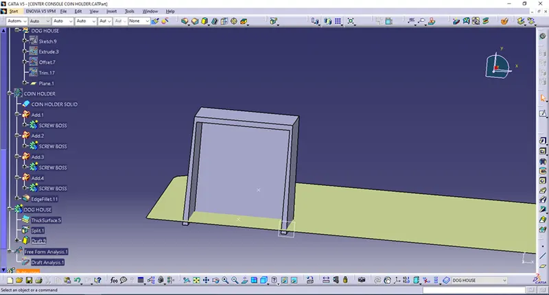
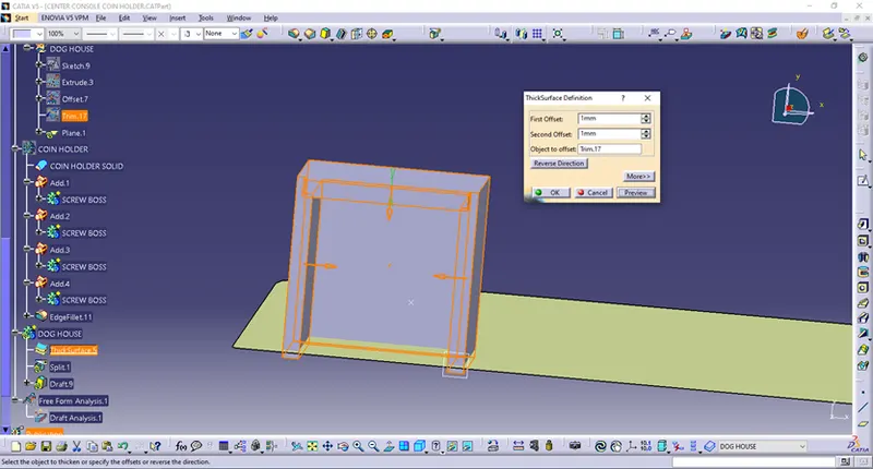
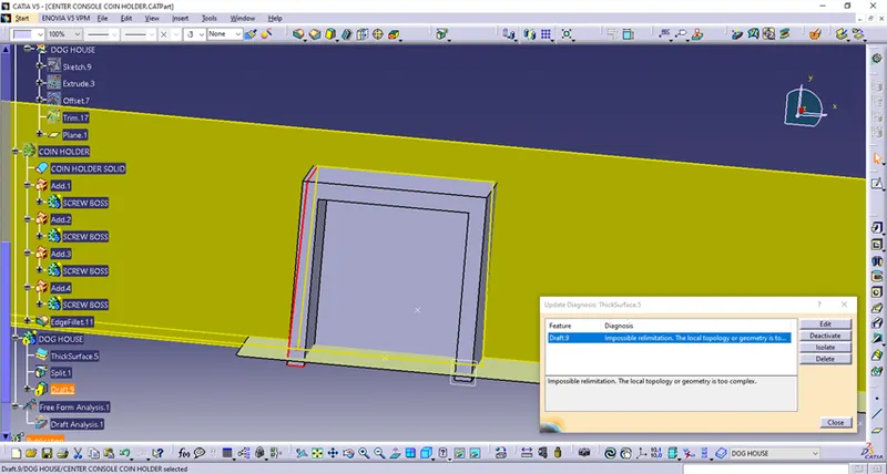
Then I have done a Draft with a Parting = Neutral option to be able to do a Draft.
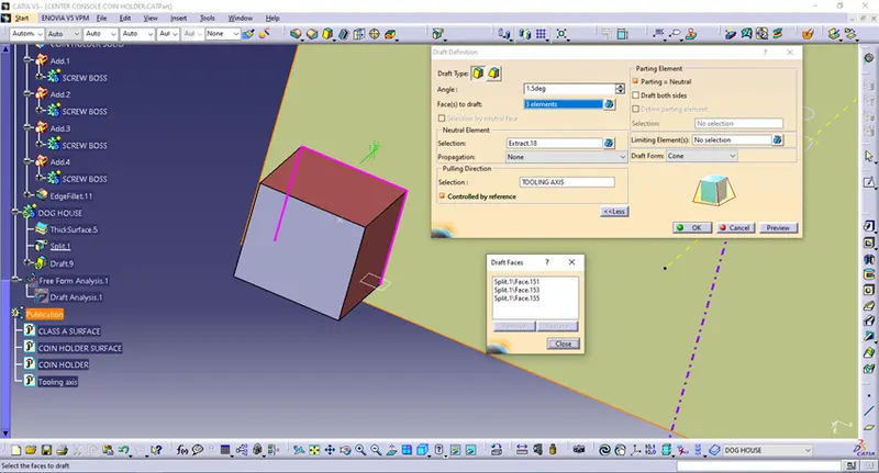
Now Draft on inner walls with SIDE TOOLING AXIS as shown.
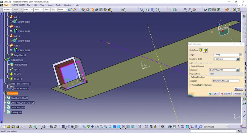
Then I have done filleting as follows.
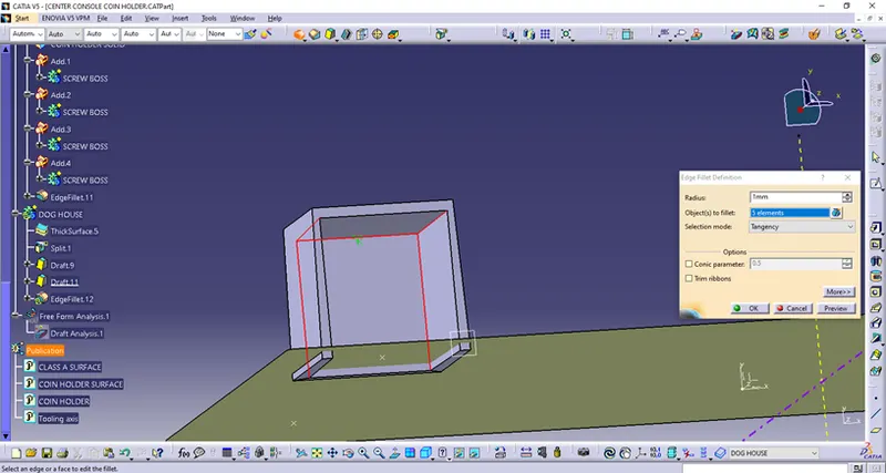
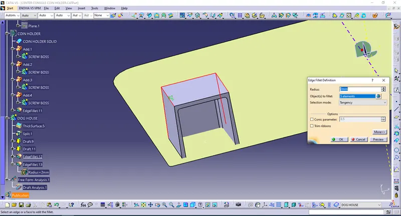
Then there is a rule for bottom walls of DOG HOUSE – wall thicknes at the bottom of DOG HOUSE = 0.4 x Part thickness ,that means – 0.4 x 2.5mm = 1mm .Height of it is 3mm - 6mm.
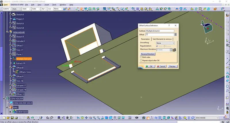
So,therefore I have extracted the inner surface and offseted it for a 1mm as shown (DOG HOUSE thickness is 1mm that is why offset is done with 1mm).Offset of bottom surface is done with 4.5mm.
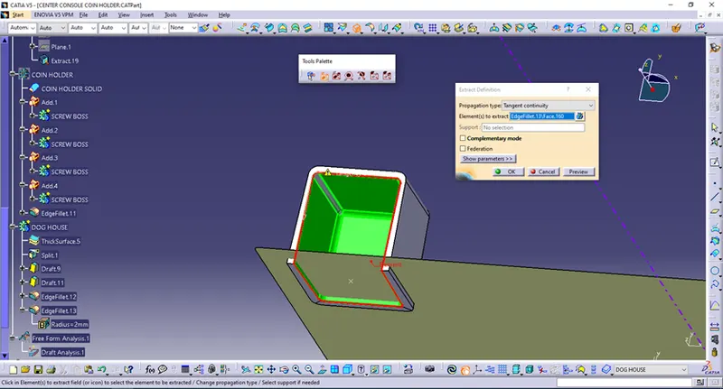
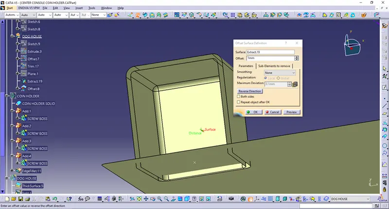
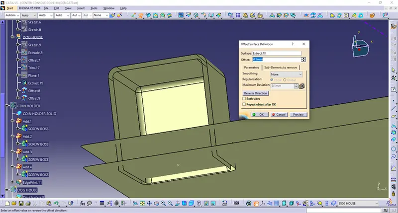
Now I have trimed those surfaces.
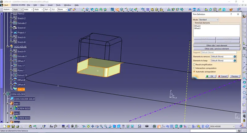
I have to extrapolate trim to be able to split DOG HOUSE with it.
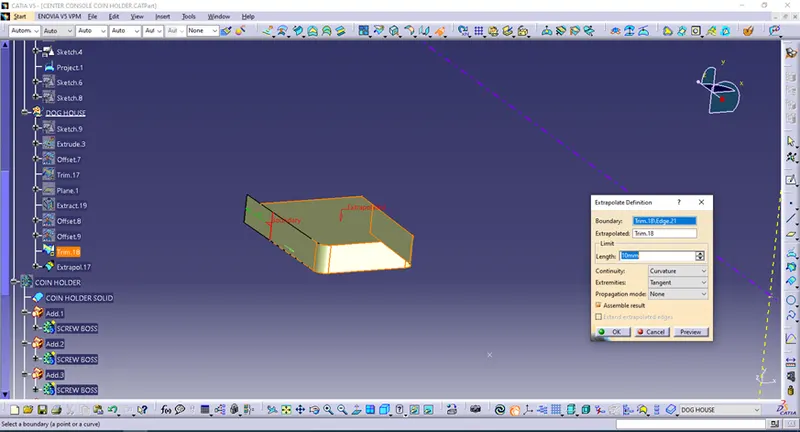
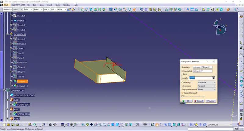
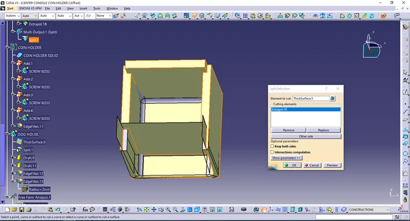
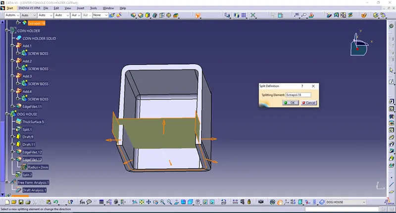
I have seen that thickness of the wall at the bottom is 1mm,but on side walls – 0.41mm.That is unsatisfactory,I have to deal with it.
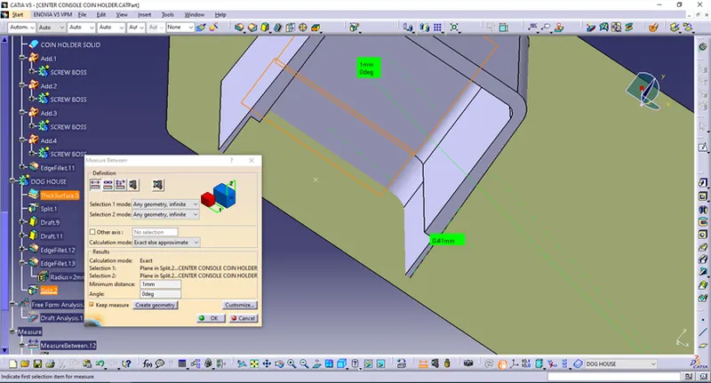
On the outward walls I have measured 91.5deg – that is OK.
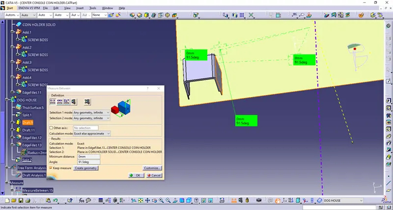
Inner walls – 91.5deg,it is also OK...but I have 0.41mm,that is not satisfactory.
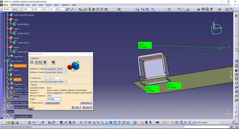
Offset with drafted sides,that is a problem...I will do offset – trim – and then draft,that should do.
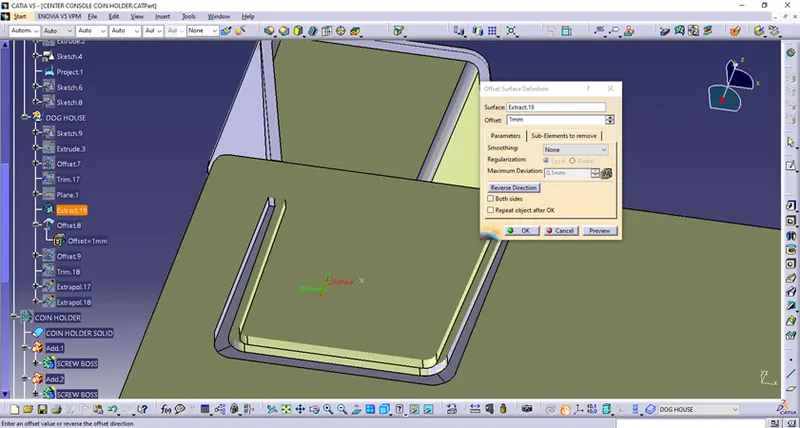
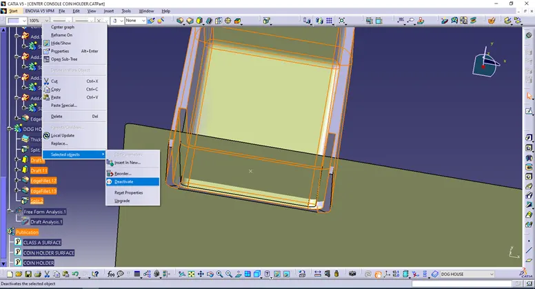
I have deactivated following features.
So,I am going back to plane,where I have done Split.
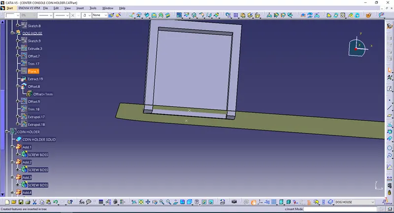
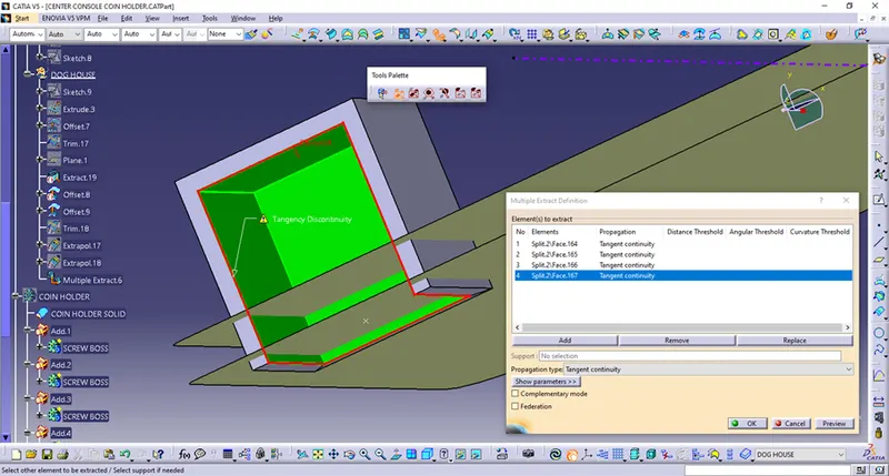
So, Offset.9 with 4.5mm is not deactivated and Extract.19 that is deactivated – I will replace it with the new ones Multiple Extract and activate deactivated features.
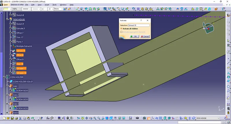
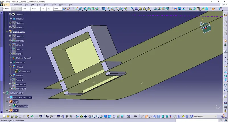
I have activated extrapolations and do the trim.
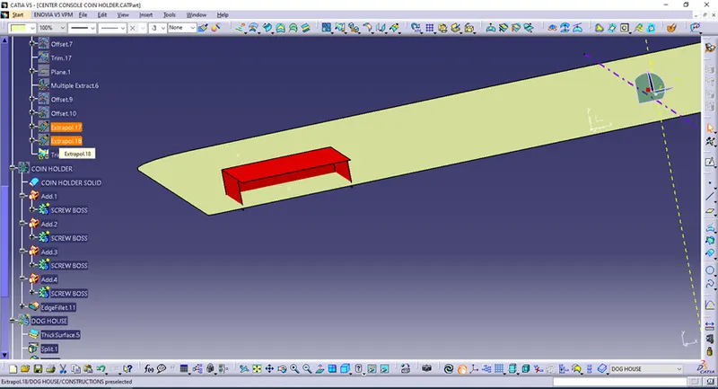
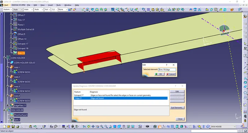
I have trimed those surfaces and split the DOG HOUSE.
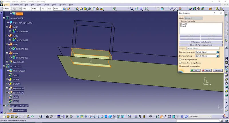
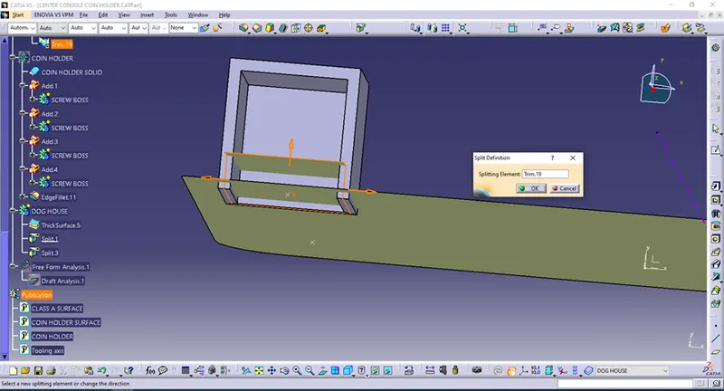
After I have done all those changes and measured all to check...I see I will get same results as before (0.41mm... unsatisfactory),that means I should do some more changes – so,I will change a values for extrude side walls (decreas it) and the draft for outer walls could stay 1.5deg but for inner walls it should change to minimum – 0.5deg.)That should do.
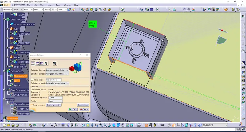
So,as I have already said
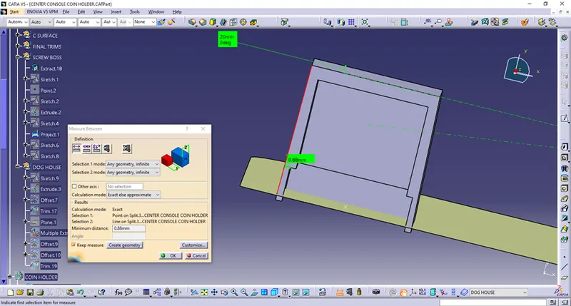
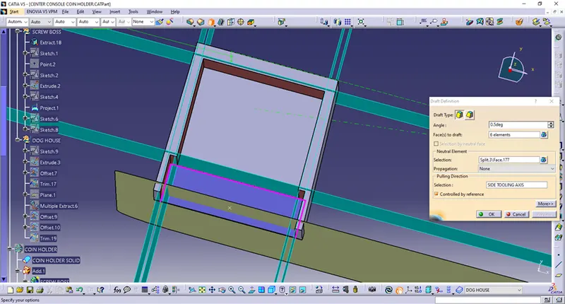
So,the value is 0.72mm (that satisfies as ±30% of 1mm),but sure to be I will decrease offset value from 1mm to 0.9mm and that value will be even greater.
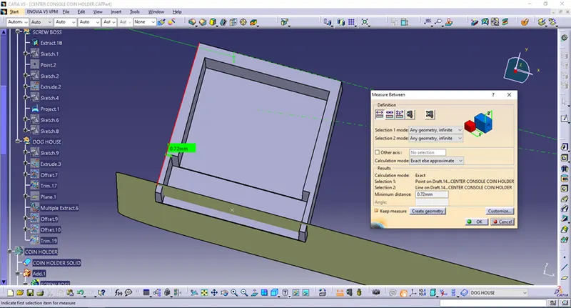
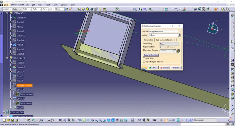
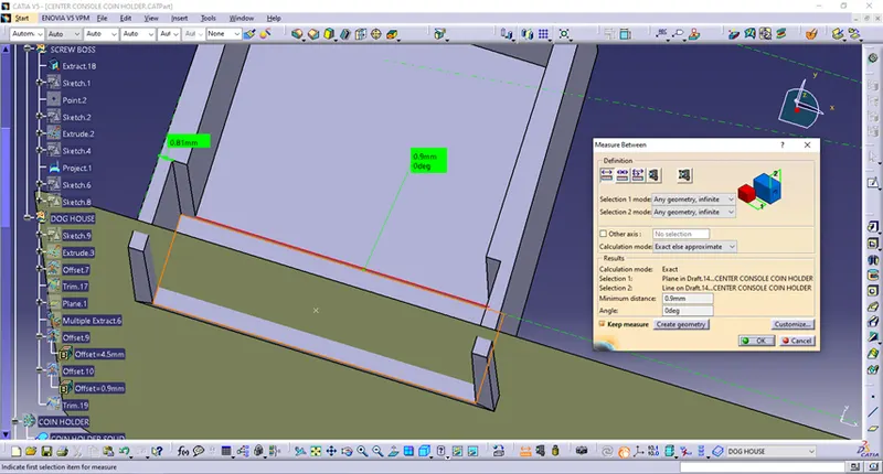
That is satisfactory,now I will do filleting once again.
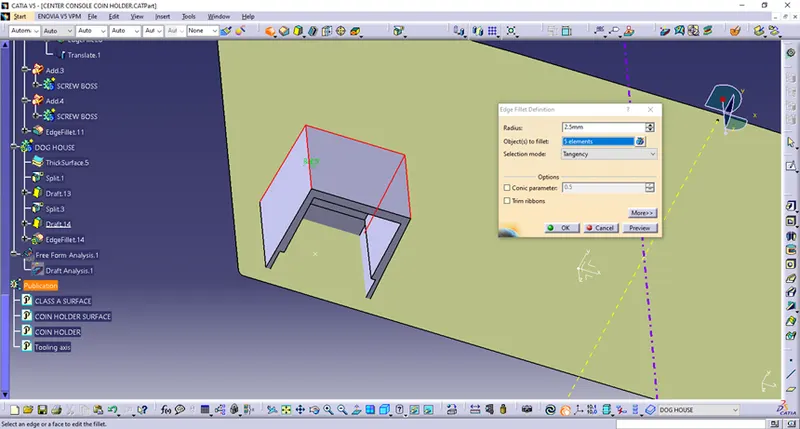
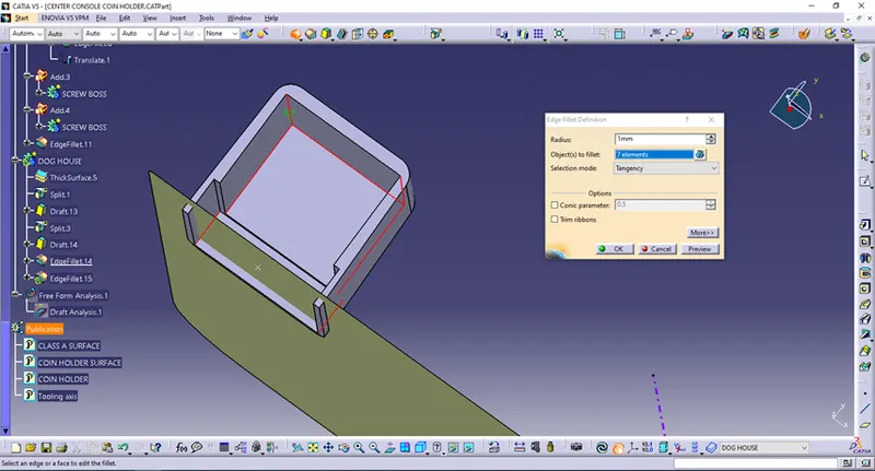
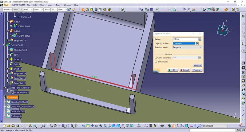
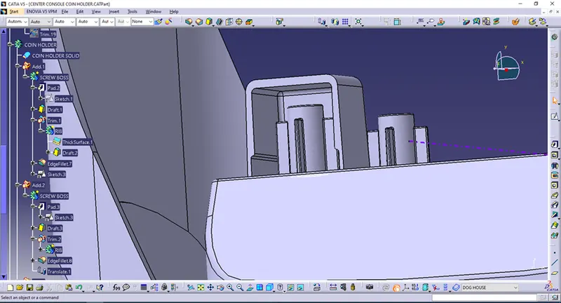
Now I will copy-paste all those DOG HOUSES and translate on required positions.
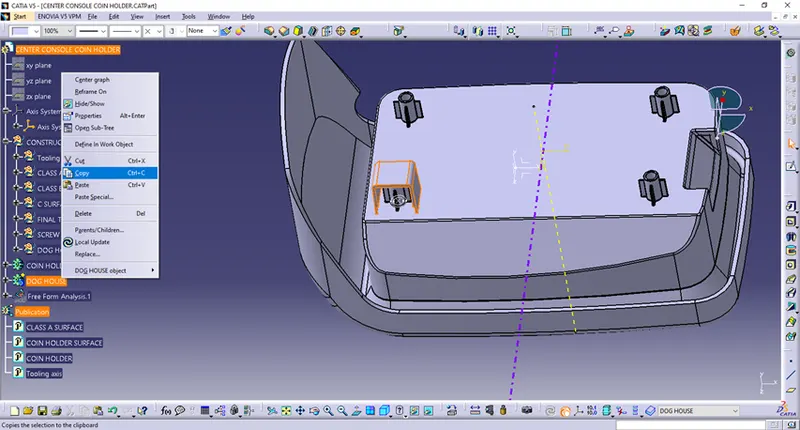
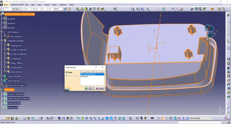
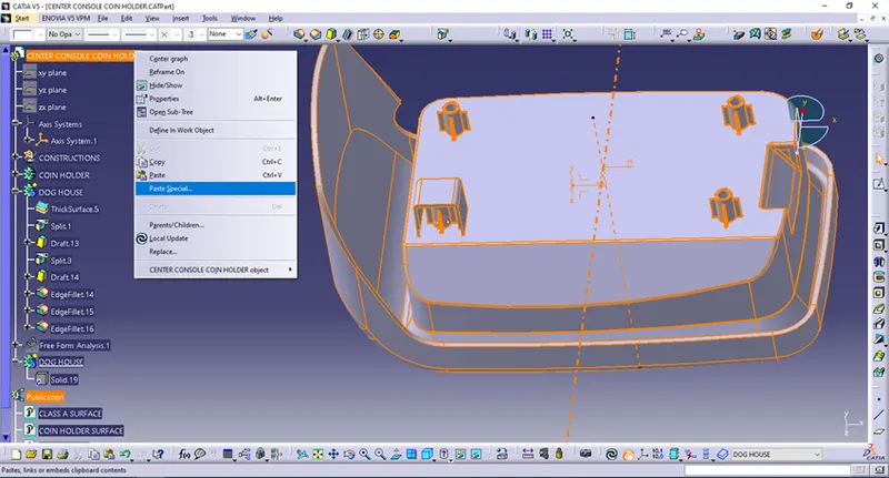
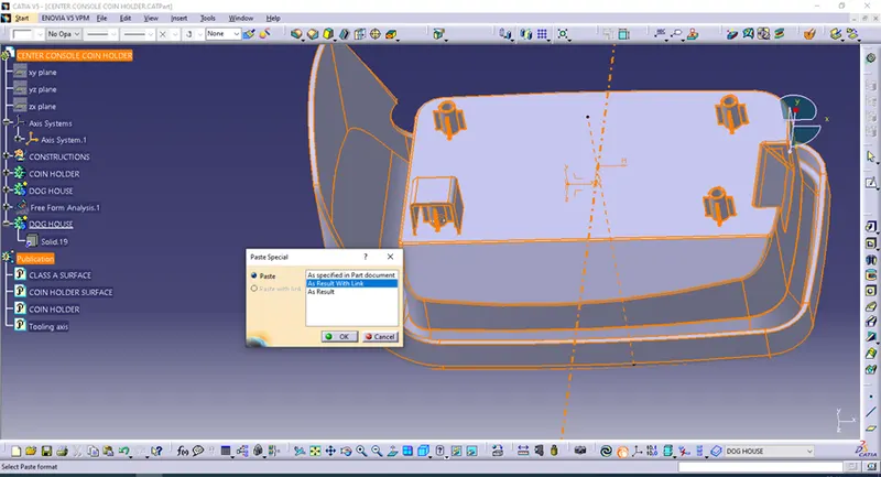
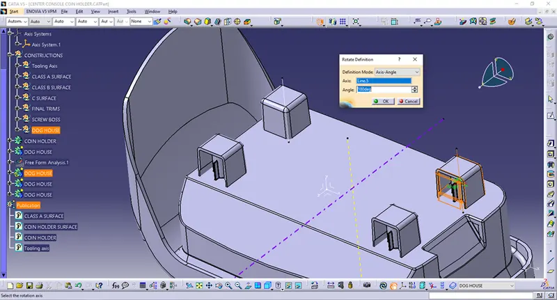
After I have done DOG HOUSE translations,I have rotate it where was needed as bellow.
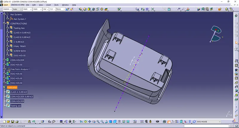
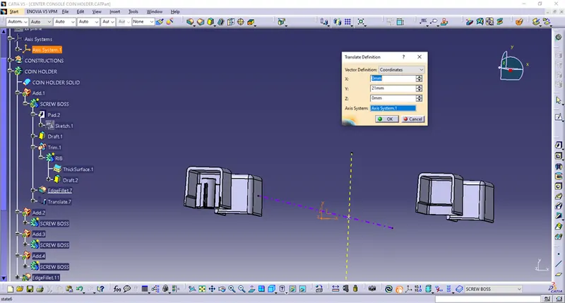
I am going to reposition SCREW BOSSes on top of DOG HOUSes.
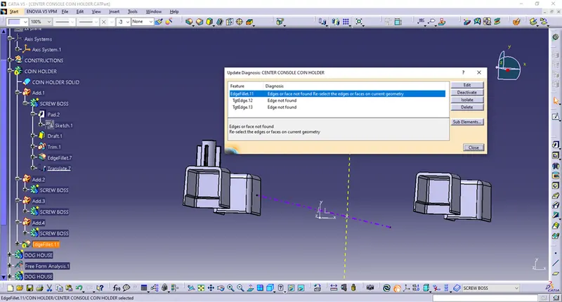
I have to made corrections to fillets – delete EdgeFillet.11.
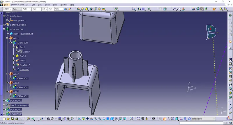
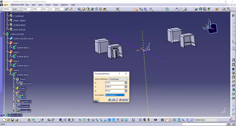
Afterwards I have joined all those DOG HOUSes with COIN HOLDER.
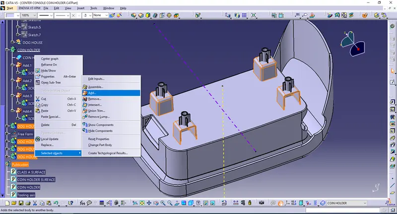
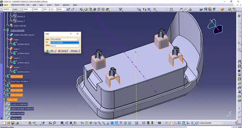
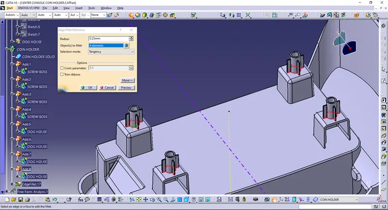
I have filleted SCREW BOSSes and DOG HOUSes as follows.
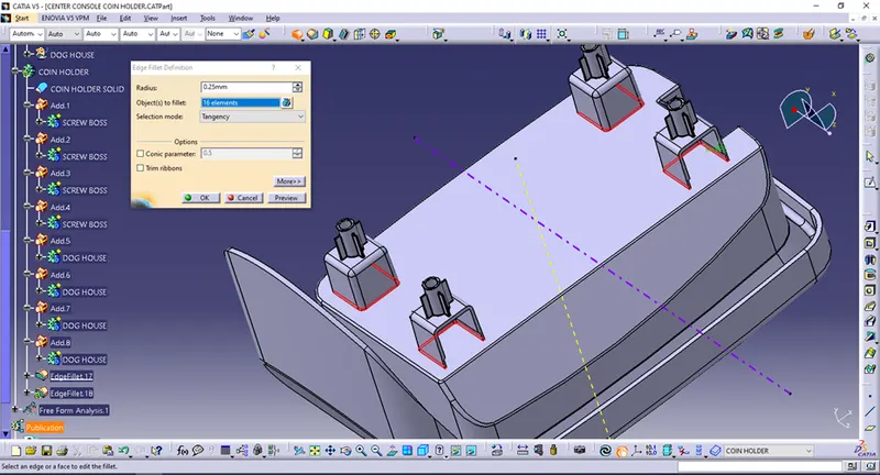
Finally I will do Draft Analysis once again with all features.
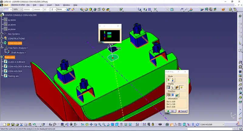
For a 1.49deg results are
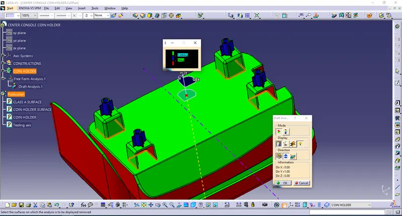
And for 0.49deg results are
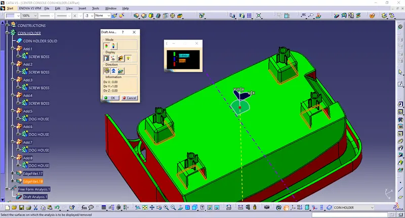
Features are good designed,drafts are satisfactory in main direction,I should investigate the part now with SIDE TOOLING AXIS also.Draft should satisfies 0.5deg angle for extrusion.
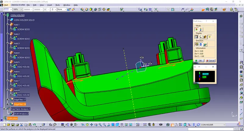
Extrusion in side direction satisfies also – part should be manufactured in two direction opening mould (mould with side core).
I am also giving various views of the COIN HOLDER with faetures SCREW BOSS and DOG HOUSE.
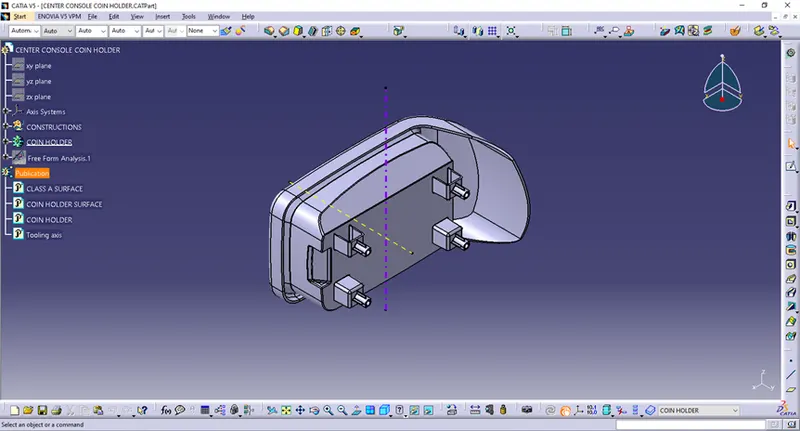
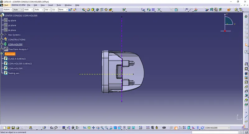
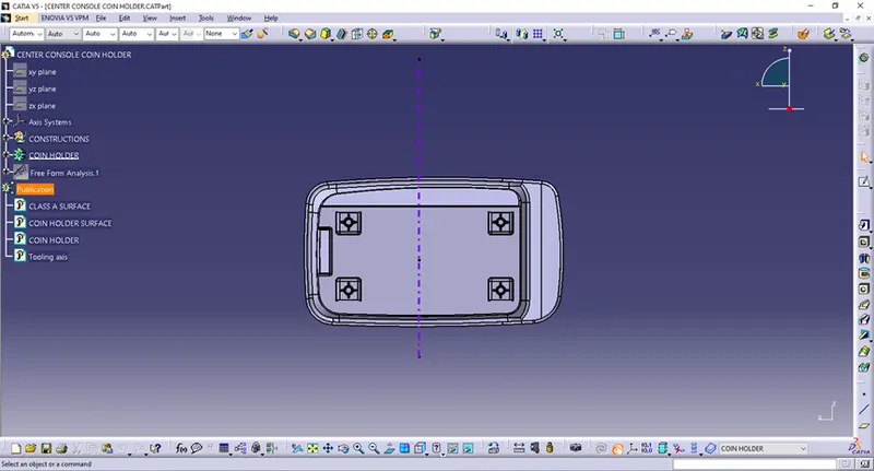
That is all fellows.
Best regards,
Ivan Tole