Week 9 - Attachment Feature Creation - Challenge 2
AIM
To Create the boss and Dog House for the Centre console coin holder considering the design rules
General Guidelines for Bosses
SCREW BOSS
Boss design in plastic parts should be as per guidelines to ensure boss strength and avoid injection molding defects.
Recommended boss wall thickness is 0.6 times of nominal wall thickness of the plastic part.
We can increase Boss wall thickness to increase its strength.
The boss can be strengthened by gussets at the base, and by attaching it to nearby walls with connecting ribs.
PROCEDURE
First to create the screw boss for the coin holder. To open the position sketch one the workbench
and create the point on the coin holder where we want
After that draw the screw boss on the position sketch as per the rule followed
And then select the part work bench and then create the new body and pad the sketck and draft the pad into 0.5 degree and also gine the fillet in all edges
after that the main method should followed in the for multiple copies
the special paste tool is used for multi copy purpose
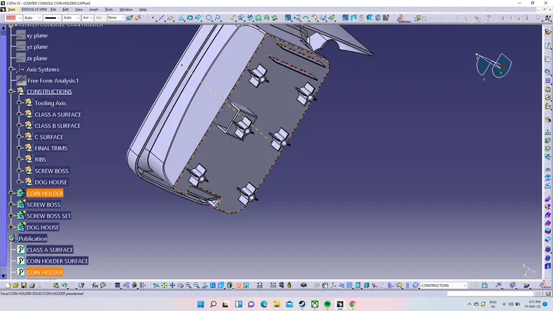
first copy the required part and paste the work body and translate into required place and this is the procedure for screw boss as show in the figure
screw boss
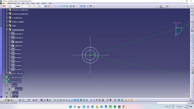
screw bos 2d sketch in the position sketch with proper dimension
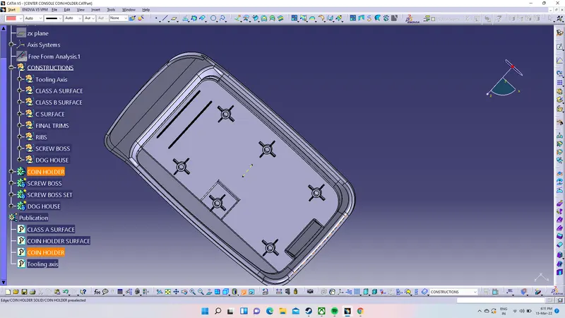
final screw boss is placed in the required part of the coin holder
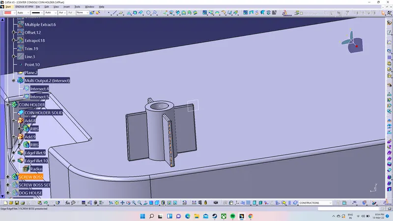
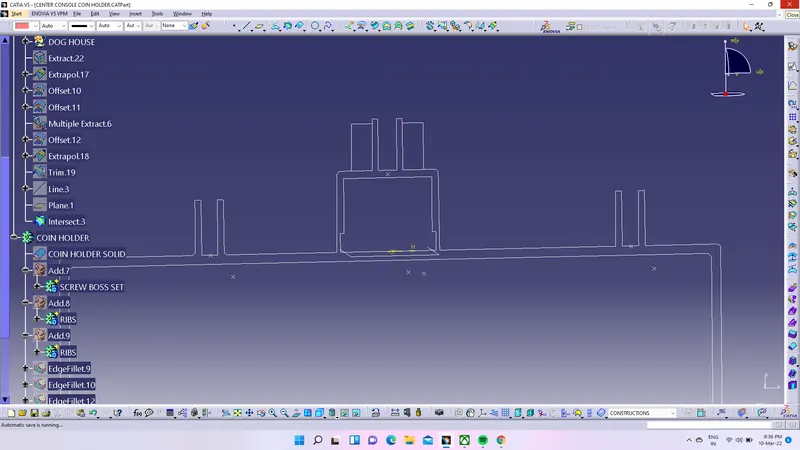
screw boss with intersection projection
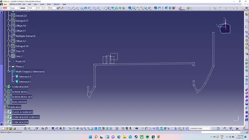
first create the plane on the screw boss after that used the intersection tool and selet the first object as part
and second object is plane.after that the instruction of the project is show in the figure
DOG HOUSE
Dog house is an engineering feature used in plastic trim design.
Dog houses are used as supporting feature.Sometimes other engineeringfeatures like snaps; locators etc. are mounded on them to increase theirstrength.
Dog houses are subjected to draft analysis to prevent breakage of the
component during ejection from mould cavity
Tooling must be cleared for easy ejection of the component, from the
core cavity.
In order to clear tooling certain value of draft is given to the
component.
Wall thickness = 0.70 x Thickness of the plastic material
Fillet on the inner side = 0.25 x Thickness of the plastic material
Fillet on the outer side = 1.25 x Thickness of the plastic material
Fillet on the coring edges = 0.25 x Thickness of the plastic material
Coring thickness = 0.40 x Thickness of the plastic material
Minimum of 2-3deg is provides on all plastic components.
PROCEDURE
create a point on coin holder and go to position sketch made is pad to a certain height as shown in
Leaving the face along the lifter, other three vertical faces of the pad component are drafted inwards, as shown inthe figure.5. Draft angle is maintained between 2 to 3 degree
create tooling direction.For dog house we have two tooling axis for top and side axis
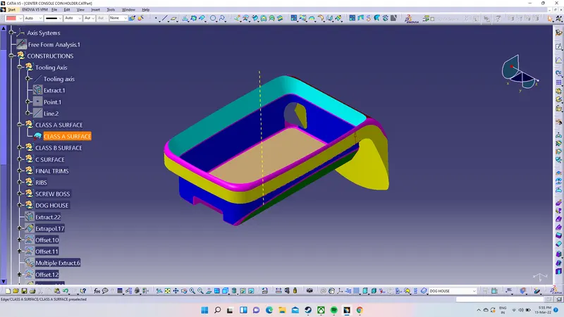
Draft again the faces parallel to the zx plane, inwards as shown in the figure Give lifter as pulling direction
The component is then subjected to shell definition. It is noted that the shell does not exceed the design relation.Wall thickness = 0.70 x Thickness of the plastic material
Draft the upper wall of the inner surface of the Dog House, to provide easy ejection of the component during manufacturing process. Draft angle is maintained between 2to 3 degree
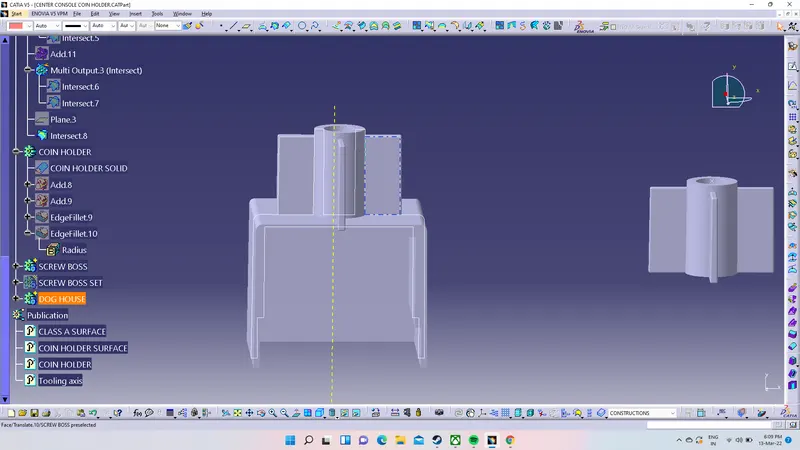
Creating fillet is the last step in the body . Fillets are created on both inner and outer side. The following relation ismaintained to create fillet.
The selected operations in the figure below are deleted to create coring.
Fillet is made and the three vertical faces excluding the facealong to the lifter. Thickness of the face is reduced to the below expression
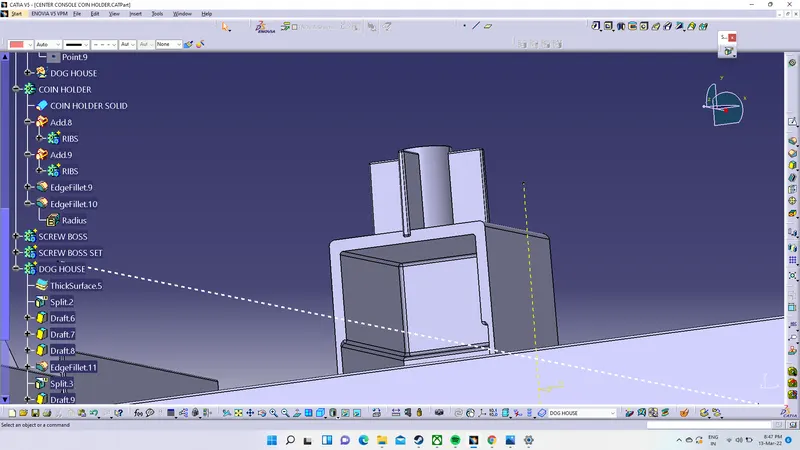
The plastic surface is extracted for offsetting using multiple extract option which is available in the GENERATIVE SHAPE DESIGN (GSD) module.
The offset value is directly proportional to the coring height. Coring height is generally maintained between 2 to 3mm.
The geometrical set named as tooling previously is changed to ENG_FEATRUE
The created offset surface is used to split the body, as shown in the figure below. Split is available in PART module under surface based features
the intersection for the dog house is under the insection tool is is used for this bisection projection