Week 9 - Attachment Feature Creation - Challenge 2
Creation of Screw boss and Dog house for the Centre Console Coin Holder
Aim: - This report aims to create the Screw boss and Dog house for the center console coin holder considering the design rules. Also, to perform draft analysis on the final component(with Screw boss and Dog house) in catiaV5(Computer-aided three-dimensional interactive application).
Objective: -
- To create the Screw boss and Dog house for the center console coin holder considering the design rules.
- To define the proper functions of Screw boss and Dog house in design parts.
- To explain the design rules considered while creating a Screw boss and Dog house in detail.
- To create the tooling axis for the coin holder model meeting the requirements of the draft angle.
- To perform draft analysis on the final component(with Screw boss and Dog house).
- To explain the bisecting method used to create the tooling axis for the coin holder model.
Theory: -
- Rib: - Rib provide a means to economical stiffness and strength in molded parts without increasing overall wall thickness.
They also facilitate: -
- Locating and arresting components of an assembly.
- Providing alignment in mating parts.
- Acting as stops or guides for the mechanism.
The examples of the Rib are shown below.
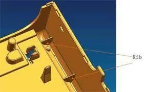
figure 01: - Example of Rib
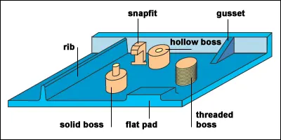
figure 02: - Example of Rib
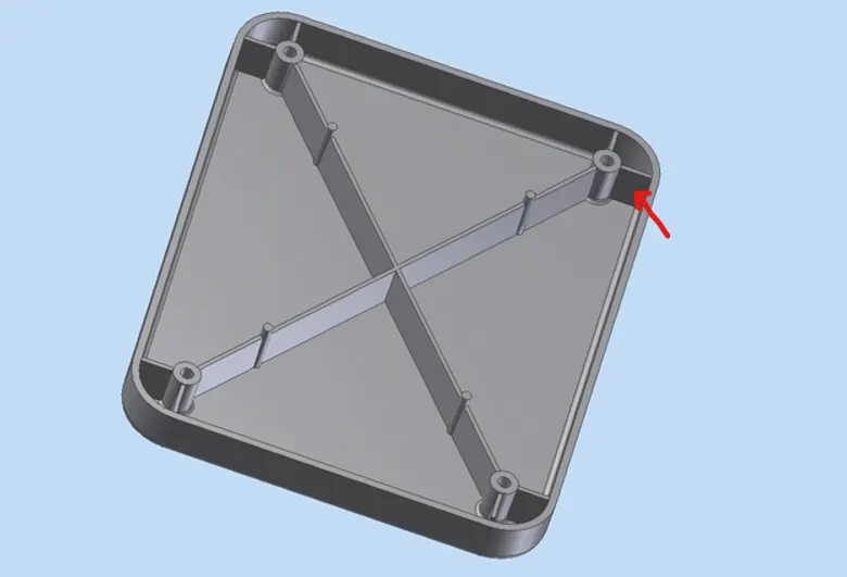
figure 03: - Example of Rib
General guidelines for Ribs and part design: -
This section deals with general guidelines for Ribs and part design.
- Proper Rib design involves five main issues: -
- Thickness
- Height
- Location
- Quantity
- Manufacturability
- Consider the below issues carefully when designing Ribs: -
Thick ribs often cause sink marks and in turn cosmetic problems on the opposite surface of the wall to which they are attached. The material, rib thickness, surface texture, color, proximity to a gate, and a variety of processing conditions determine the severity of the sink.
Sink marks are the areas in a molded part where the surface is deformed into a depression. The depressions typically occur in areas of thick geometry and are caused by uneven cooling of the injection material. This shrinking begins pulling the outer surface in, potentially collapsing the wall or deforming the part. The example of the sink mark is shown in figure 04.
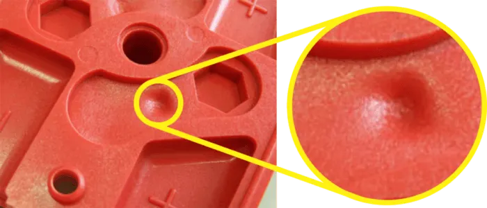
figure 04: - Example of the Sink mark in plastic part
Highly glossy, critical surfaces may require thinner ribs. Thin-walled parts(<1.5 mm) can often tolerate ribs that are ticker than the percentage in the guidelines. On parts with a wall thickness of 1 mm or less, the rib thickness should be equal to the wall thickness. Rib thickness also directly affects moldability. Very thin ribs can be difficult to fill. Because of flow hesitation, thin ribs near the gate can sometimes be more difficult to fill than those further away. Flow entering the thin ribs hesitates and freezes while the thicker wall section fills. Ribs usually project from the main wall in the mold opening direction and are formed in blind holes in the mold steel. Ribs generally require at least one-half degree of draft per side to facilitate part ejection from the mold. More than 1 degree of draft per side can lead to excessive rib thickness reduction and filling problems in tall ribs.
Generally, Taller ribs provide greater support. To avoid mold filling, venting, and ejection problems, standard rules of thumb limit rib height to approximately 5x the rib-base thickness. Because of the required draft for ejection, the top of tall ribs may become too thin to fill easily. Additionally, very tall ribs are prone to buckling under load. If you encounter one of these conditions, consider designing two or more shorter, thinner ribs to provide the same support with improved moldability as shown in figure 05. Maintain enough space between ribs for adequate mold cooling: for short ribs allows at least two times the wall thickness.
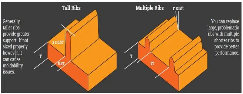
figure 05: - Example of multiple Ribs
2. Screw Boss: -
They are used to aid in the assembly of molded parts by providing a channel for a screw. Designing plastic screw bosses is fairly straightforward but there are a few considerations to ensure a strong connection between parts and mitigate cosmetic defects. The examples of screw bosses are shown below. Bosses are design elements that strengthen parts. We’re going to unpack why you should have bosses, how to design them appropriately, and some common part failures which can be avoided by using them. Bosses serve two purposes. Their primary use is to strengthen holes or slots in the surface of your part.
The secondary use of bosses is to create points at which your assembled product can be fastened together. Injection molding is all about speed, and not just in the actual molding. Properly designed plastic parts bring down costs by being designed for rapid assembly. Take apart a high-quality plastic product, and it should be easy to put it back together again. The bosses should line up and show you how parts fit, and then those bosses should hold the parts in place, ready for a fastener or clip to permanently fix them in place.
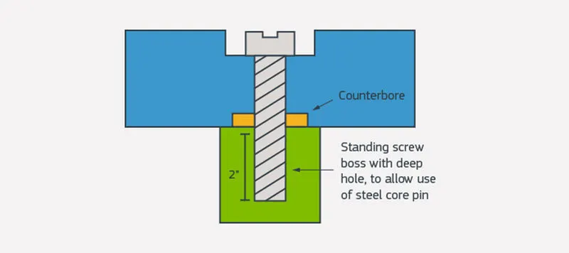
figure 06: - Example of Screw boss
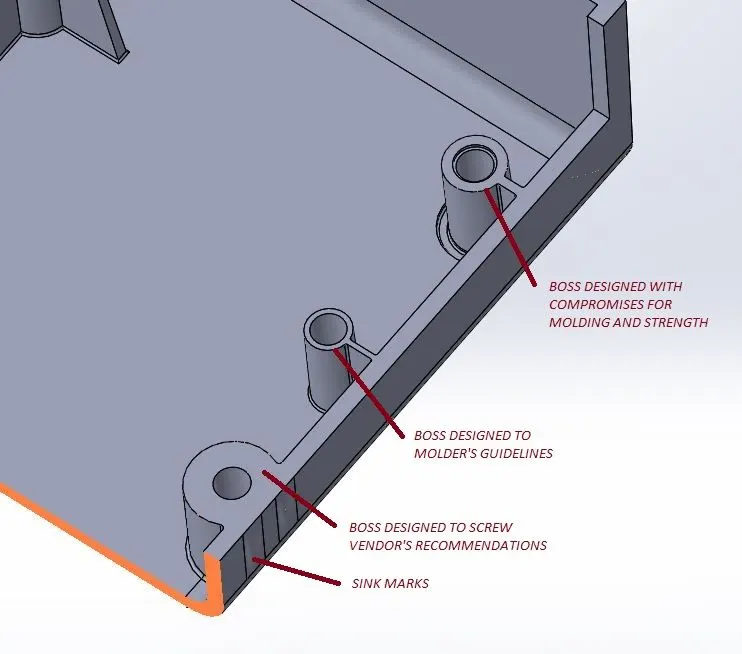
figure 07: - Example of different screw bosses
Bosses find use in many part designs as points for attachments and assembly. The most common variety consists of cylindrical projections with holes designed to receive screws, threaded inserts, or another type of fastening hardware. As a rule of thumb, the outside diameter of bosses should remain within 2.0 to 2.4 times the outside diameter of the screw or insert.
Avoid bosses that merge into sidewalls because they can form thick sections that lead to sinking. Instead, position the bosses away from the sidewalls, and if needed, use connecting ribs for support. Consider using open boss designs for bosses near a standing wall as shown in figure 08.
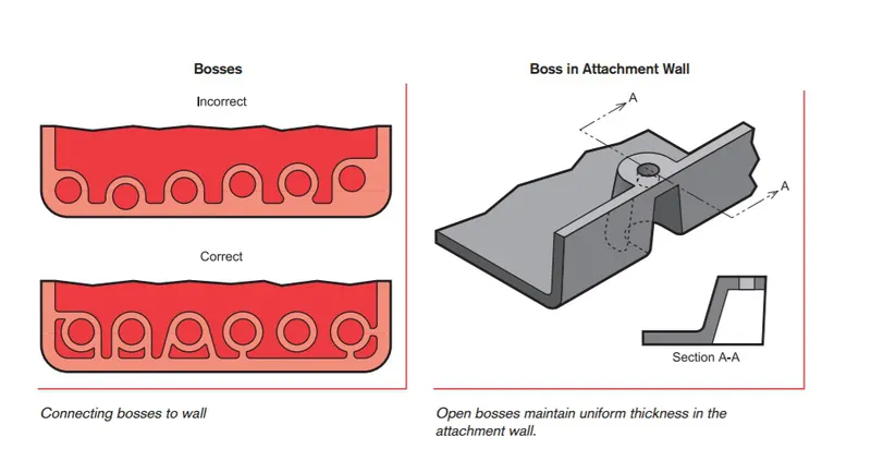
figure 08: - Screw bosses with different orientations
General guidelines or rules for a Screw boss are as follow: -
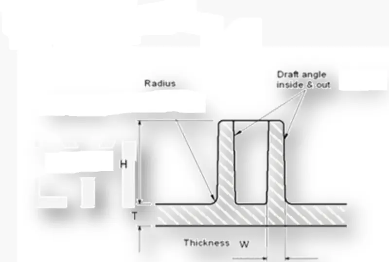
figure 09: - Design rules for a Screw boss
As shown in figure 9, the draft angle should be ≥ 0.5 degrees. Width (W) on one side of the wall should be 0.6*nominal wall thickness (T). The height to diameter ratio is 3:1. Optional 0.25 mm maximum should be the fillet radius. Boss gussets must meet rib guidelines. Need to plan for the type of ejection. If less than 25 mm tall, the draft is not required when sleeve ejection is used. Over 25 mm tall, the draft is required on the outside wall only if sleeve ejection is used. If sleeve ejection is not used then the draft is required on all walls.
3. Dog House: -
The primary function of the dog house is to avoid sink marks and the secondary use of a dog house is to locate screw bosses and other features on it depending on the tooling directions and other aspects. The general rules or guidelines are shown below. The dog house is an engineering feature used in the plastic trim design. Dog houses are used as supporting features. Sometimes other engineering
features like snaps; locators,s, etc. are mounted on them to increase their strength. Dog houses are subjected to draft analysis to prevent breakage of the component during ejection from the mold cavity. Dog house and other engineering components are built on B-surface.
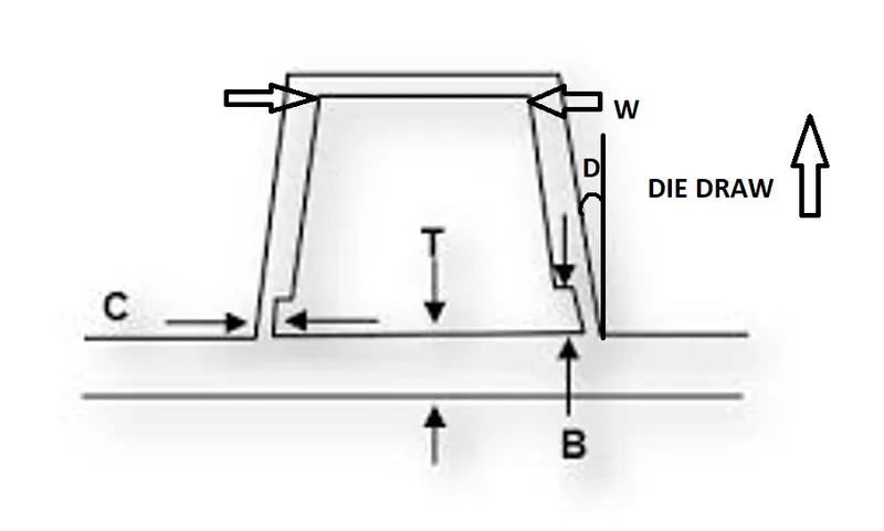
figure 10: - Design rules for Dog house
As shown in figure 10, the minimum doghouse width (W) for doghouses is 12 mm. 3:1 is the ratio of steel width to height. 2:1 is preferred. The minimum draft for doghouses is 1.5 degrees to die drawing. If a slide is considered then this requirement can change to 3 degrees minimum. Doghouse wall thickness at the intersection of part (C) should be 40% or less than main wall stock (T). Height (B) should be between 3 to 6 mm.
4. Tooling axis creation for coin holder model(with Screw boss and Dog house): -
The tooling axis indicates the direction along which the tooling or the manufacturing of the component will be done. In CATIA, the tooling axis is used to create C surfaces using the sweep option. There are many methods for the creation of the tooling axis and bisecting method is one of them.
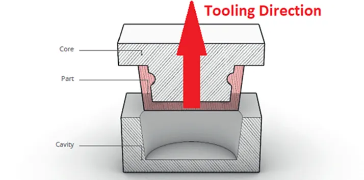
figure 11: - Example of tooling axis direction
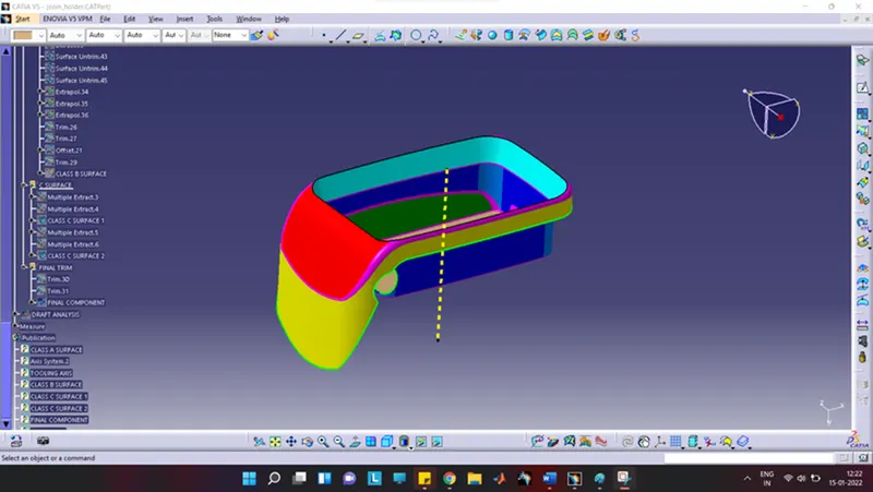

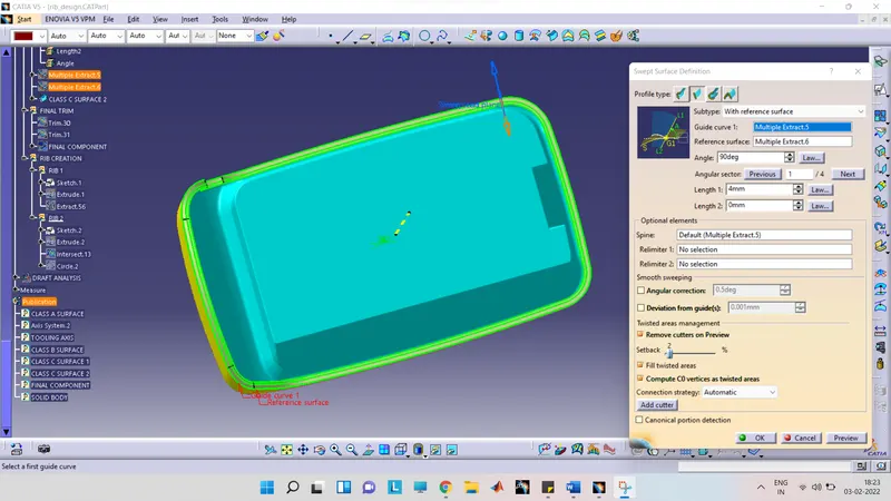
figure 12: - Use of tooling axis in CATIA (C surface)
The steps involved in creating tooling axis using the bisecting method are as follow: -
- Check continuity or quality of Class A surface
- Selection of best possible tooling direction
- Creating dummy tooling axis
- Tooling clearance for respective directions
- Creating final tooling axis
step1: - Check continuity or quality of Class A surface
Product designers should check the continuity or quality of the class A surface given by the class A engineer. They should ensure that there are no gaps between the surfaces using the boundary or the join command in CATIA.
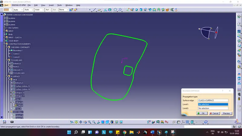
figure 13: - Checking the continuity (using boundary command)
step2: - Selection of best possible tooling direction
The tooling direction should be in such a way that it should cover the complete component along with its holes, undercuts, etc. in the main tooling. The product designer should also avoid side cores because the side cores generally increase the manufacturing cost of the component.
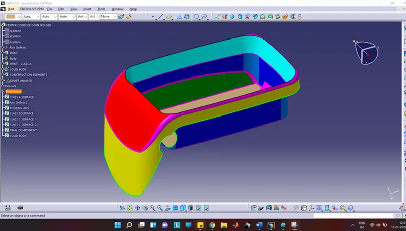
figure 14: - Coin Holder Model
After checking all the directions of the model shown in figure 14, it is found that most of the faces in the model are without a draft like shown in figure 15. Hence, the manufacturing of such components is impossible. A product designer should immediately concern the Class A engineer for such cases.
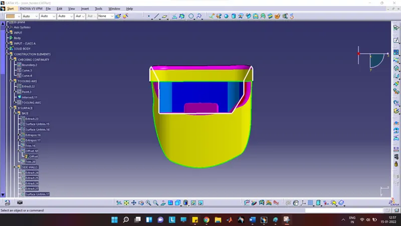
figure 15: - x-direction
Just for time being to continue the design further for creating the final component out of the surface model, one can select the y-direction as a tooling direction as shown in figure 16.
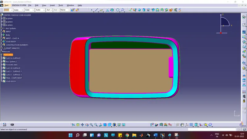
figure 16: - y-direction
step3: - Creating dummy tooling axis
The dummy tooling axis is a line or an axis created at the center along the y-direction as shown in figure 17. The dummy tooling axis is used just as a reference and it is not the real tooling axis.
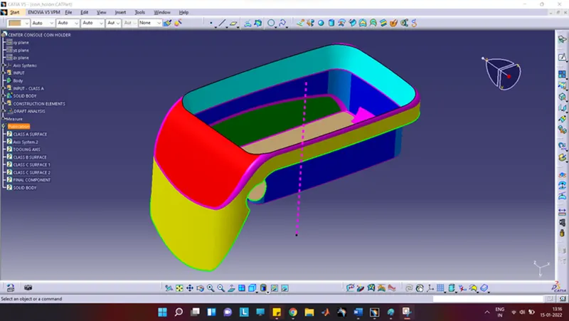
figure 17: - Dummy tooling axis
step4: - Tooling clearance for respective directions
This step is skipped because we directly chose y-direction as our tooling direction as shown in figure 16 and made the tooling axis directly for the y-direction taking the center of the component as shown in figure 18. There is no involvement of bisecting method in this case.
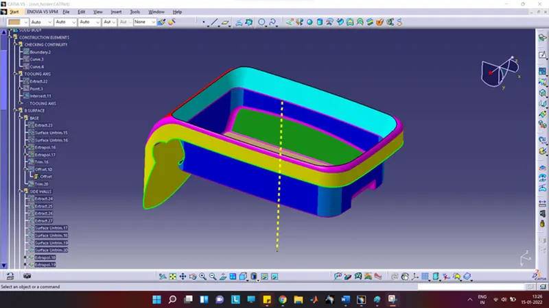
figure 18: - Main tooling axis
5. Publication: -
Using the publication option, the important parts of a model are easy to search.
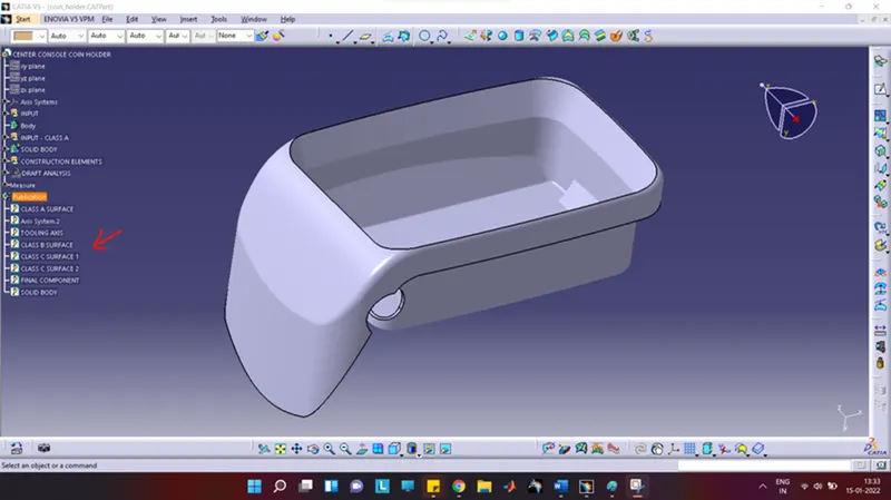
figure 19: - Coin Holder Model, Class A, B, and C and tooling axis are easy to search
6. Draft Analysis on Coin Holder Model (with Screw boss and Dog house): -
Draft: - Draft is providing angles or tapers on product features such as walls, ribs, posts, and bosses that lie parallel to the direction of release from the mold that eases the part ejection.
The draft is required on all parts in the direction of mold movement to allow parts to release or eject from the mold properly. The draft is the angle at which the part is tapered to allow it to release. As the part cools, it tends to shrink to the core side of the mold. Adding draft helps the part to release. 3 degrees is the nominal draft. Whereas, 0.5 degrees can also be manufactured at ribs. 7 degrees for the textured faces.
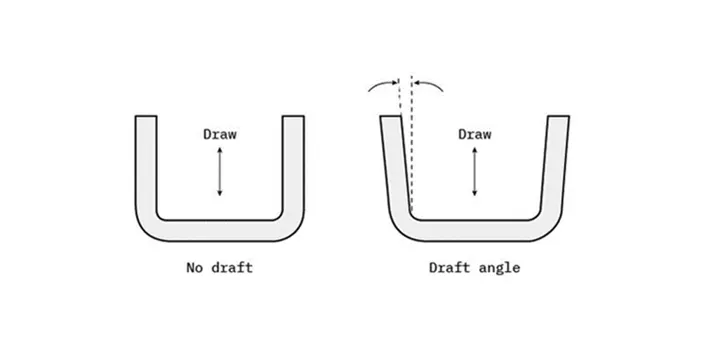
figure 20: - Example of draft
Draft analysis is used to confirm the appropriate draft angle required for the component that is to be manufactured. Quick analysis mode, show or hide color scale, and analysis under the running point are the three main features used in the draft analysis. The color scale shows the draft angle for different colored areas and the analysis under the running point shows the draft angle at different points.
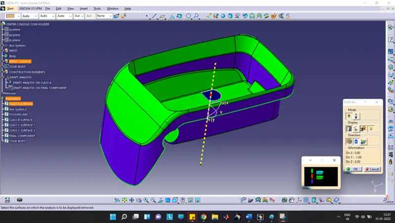
figure 21: - show or hide the color scale
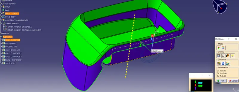
figure 22: - Analysis under the running point
Satisfaction of Rules: -
1. For Screw boss: -
figure 23: - For reference
Rule 1: - Width(W)
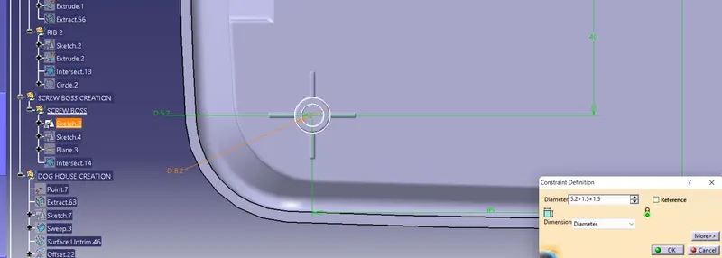
Since width on one side of the wall should be 0.6*nominal wall thickness i.e 0.6*2.5 (nominal wall thickness of coin holder) = 1.5 mm on each side of the wall. Hence, the outside diameter will be 5.2 (diameter for M6 hole) + 1.5+1.5 = 8.2 mm as shown in above figure.
Rule 2: - Draft
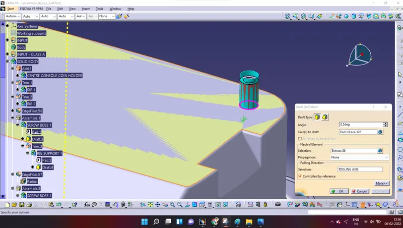
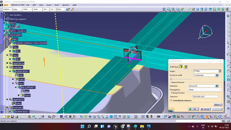
Since the draft angle should be ≥ 0.5 degrees and also we have selected 0.5 degrees as our draft angle for the boss as well as for rib support as shown in the above figures. Hence, this rule is satisfied.
Rule 3: - Fillet radius
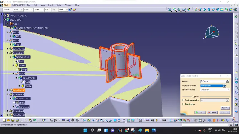
Since the Optional 0.25 mm maximum should be the fillet radius and also we have selected 0.25 mm as our fillet radius in the screw boss. Hence, this rule is satisfied.
Rule 4: - Height (H)
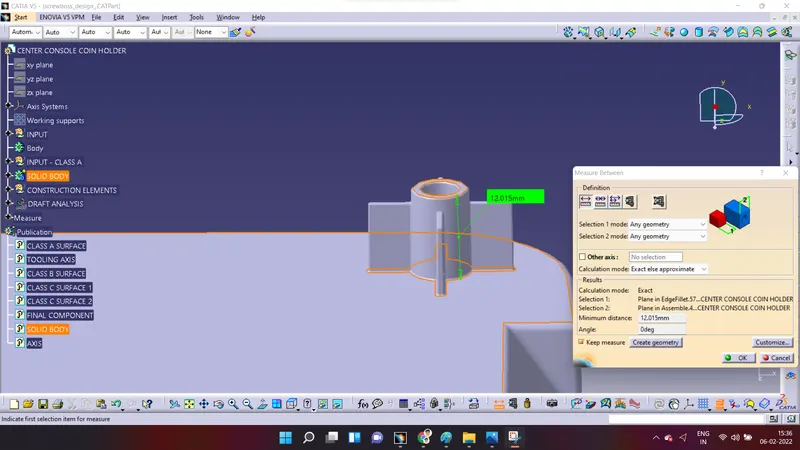
Since, the height to diameter ratio is 3:1 i.e H = 8.2*3 = 24.6 mm. The height we kept of our screw boss is 12 mm which doesn't support the rule.
2. For Dog house: -
figure 24: - For reference
Rule 1: - Width (W)
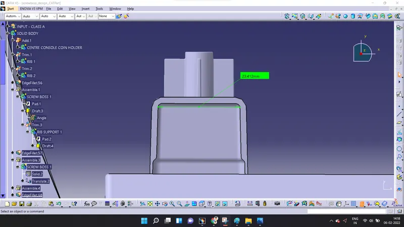
Since the minimum doghouse width (W) for doghouses is 12 mm and we kept 23 mm as shown in the above figure. Hence, this rule is satisfied.
Rule 2: - Draft
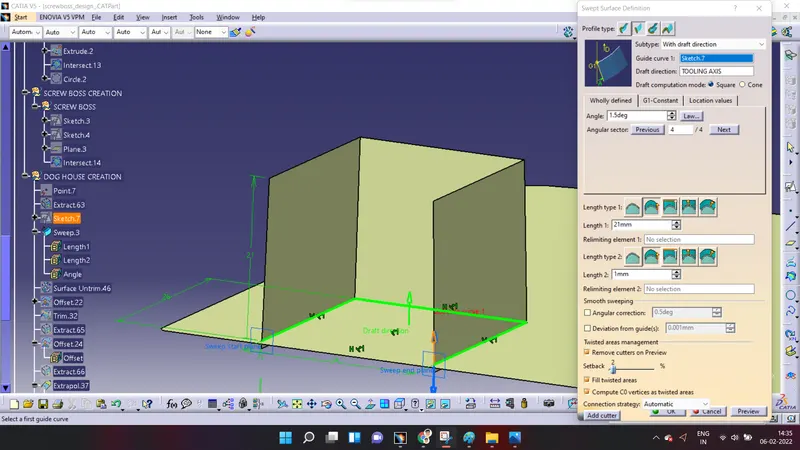
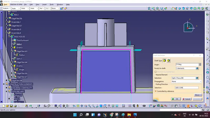
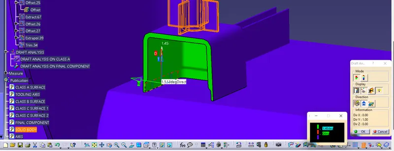
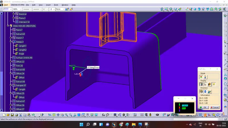
The minimum draft for doghouses is 1.5 degrees to die drawing and we kept 1.5 degrees in tooling direction and 0.5 degrees in side-core direction as shown in the above figures. Hence, this rule is satisfied.
Rule 3: - Height (B)
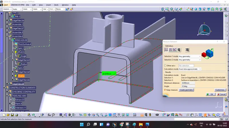
Since Height (B) should be between 3 to 6 mm and we kept it as 4 mm as shown in the above figure. Hence, this rule is satisfied.
Rule 4: - Doghouse wall thickness at the intersection of part (C)
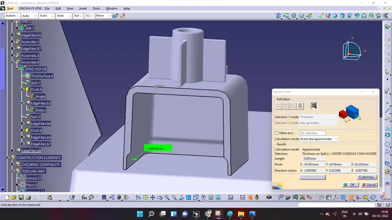
Since the doghouse wall thickness at the intersection of part (C) should be 40% or less than main wall stock (T) i.e 0.4*2.5 (nominal wall thickness) = 0.4*2.5 = 1 mm as shown in the above figure. The thickness (C) will be varying at different points because of the given draft.
Rule 5: - Height
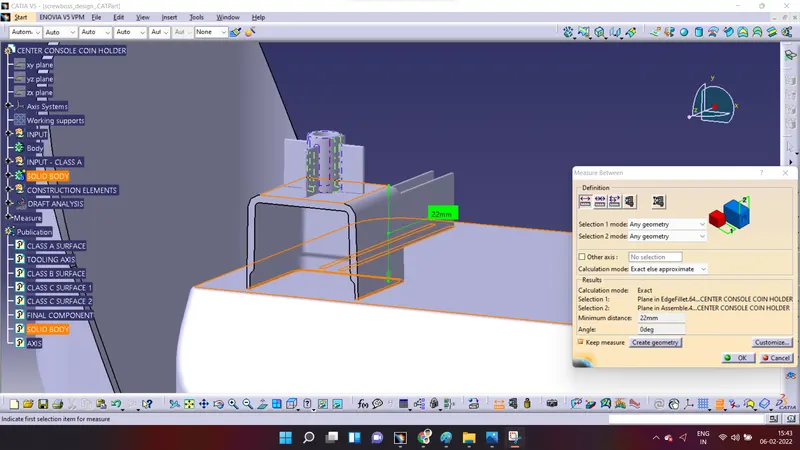
Since 3:1 is the ratio of steel width to height i.e H = 23/3 = 8 mm and we kept 22 mm as shown in the above figure. Hence, the rule is satisfied.
Screenshots of the Draft analysis report: -
- Screenshots of the Draft analysis report for Class-A surface: -
- Image of the complete Draft analysis: -
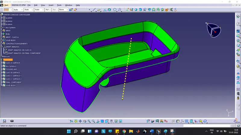
2. Images of the color scale variant: -
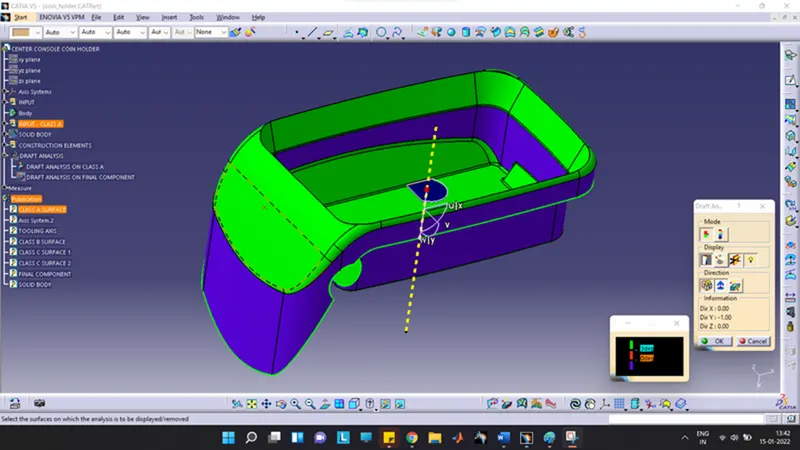
3. A model with the proper color code of the draft angle in various orientations (Isometric, Front, Side, and Top View): -
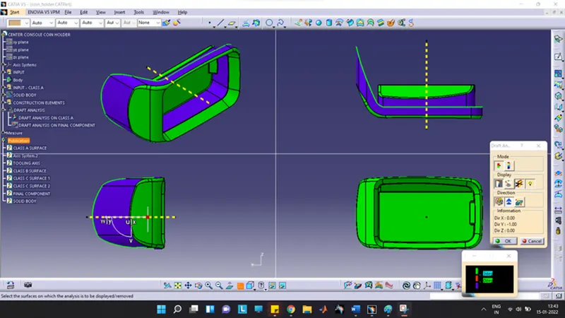
- Screenshots of the Draft analysis report for the final plastic component(with Screw boss and Dog house): -
- Image of the complete Draft analysis: -
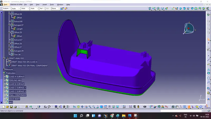
2. Images of the color scale variant: -
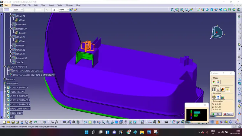
3. A model with the proper color code of the draft angle in various orientations (Isometric, Front, Side, and Top View):
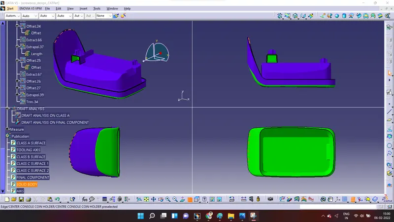
Other images: -
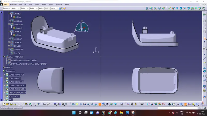
- Final component with Screw boss and Dog house
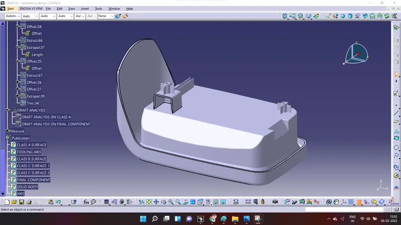
- Screenshots of the completed design in various orientations (Isometric, Front, Side, and Top View)
- Dog house analysis images
1. Draft of 1.5 degrees in the direction of the main tooling
2. Draft of 0.5 degrees in the direction of side cores
Conclusion: -
- Plastics designers love thin walls, but thin and strong are opposites ends of the trade-off spectrum. Bosses are the happy medium, reinforcing fracture-prone features like screw holes, penetrations, or mounting slots without impacting the cost or looks of a design.
- Troubleshooting different problems while operating on software is one of the skill-enhancing techniques.
- Dog houses are the sink preventers.
- While operating on software, if one gets a feature involved in an update cycle error then one out of the two sketches or features which are interrelated to each other should be isolated.
- Formulation in dimensions can help an individual to manage more complex and bigger problems.