Week 9 - Attachment Feature Creation - Challenge 2
SCREW BOSS AND DOG HOUSE DESIGN
OBJECTIVE
- To design a screw boss by applying all design constraints.
- To design a dog house by applying all design constraints.
- To perform draft analysis.
INTRODUCTION
SCREW BOSS
The screw boss is an attachment feature. It helps in locating and fastening the components together at mating locations.
DOG HOUSE
Dog house in also a kind of attachment feature used in plastic components. It is used where the screw boss requires additional height. We cannot directly impart more height to screw boss, this might leads to sink waves in component. It also used for mounting fasteners, snaps,etc.
SCREW BOSS DESIGN RULES
- THICKNESS (W)
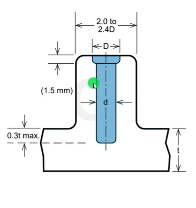
Screw boss thickness should be 0.4 or 0.5 times the wall thickness. Very thin results in poor mold filling ability.
W = 0.4 * t mm
In this case the outer diameter of boss is 2.4 times screw diameter used.
- FILLET RADIUS
Optimal fillet radius is 0.25mm.
- HEIGHT
Height to diameter ratio taken is 3:1 for steel whereas the nominal ratio is 2:1. It can project up to 0.3 times wall thickness of component.
- DRAFT
The minimum draft for boss walls is 0.5 degrees.
- Bosses can’t be attaches to side walls. This might leads to runner lines and sinkage of material. We can either provide connecting ribs for bosses or open boss design for bosses near side walls.
 '
'
SCREW BOSS DESIGN
- Importing the coin holder component into CATIA interface.
- Sketch the boss profile in the base surface.
- Inset a new body.
- Pad the profile. Thicken it.
From design rule,
I am choosing a M6 bolt. Its major diameter will be 6mm. Tap drill size would be approximately 5.5mm.
Outer diameter D = 2.4 * d
= 2.4 * 5.5
= 13.2mm
- Change the extruded height to 15mm
- Draft is given of about 0.5 degrees.
From design rule,
The minimum drat angle for boss is +/- 0.5 degrees.
- All the edges are given 0.25mm maximum fillet radius.
- Now we can create ribs on bosses to stiffen it.
- Extract the surface on which the rib is to be designed.
- Draw a line and extrude it to create a surface.
- Inset a new body
- Thicken the surface by 1mm.
From design rule,
W = 0.4 * t
= 0. * 2.5
= 1mm
- Change the extruded height to 12.5mm
From design rule,
H = 5 * t
= 5 * 2.5
= 12.5mm
- Draft is given of about 0.5 degrees.
From design rule,
The minimum drat angle for ribs is +/- 0.5 degrees.
- All the edges are given 0.25mm maximum fillet radius.
- Now creating another rib spaced at 5mm.
From design rule,
As per 3:1 ratio
Height /Width = 3/1
Width = 12.5/3
Width = 4.166mm
That is approximately 5mm.
FRONT VIEW
TOP VIEW
SIDE VIEW
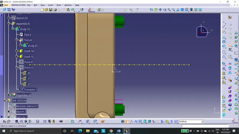
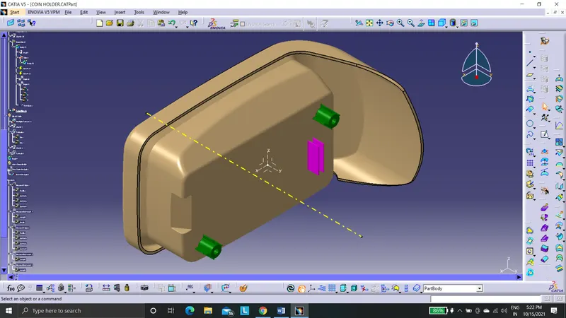
ISOMETRIC VIEW
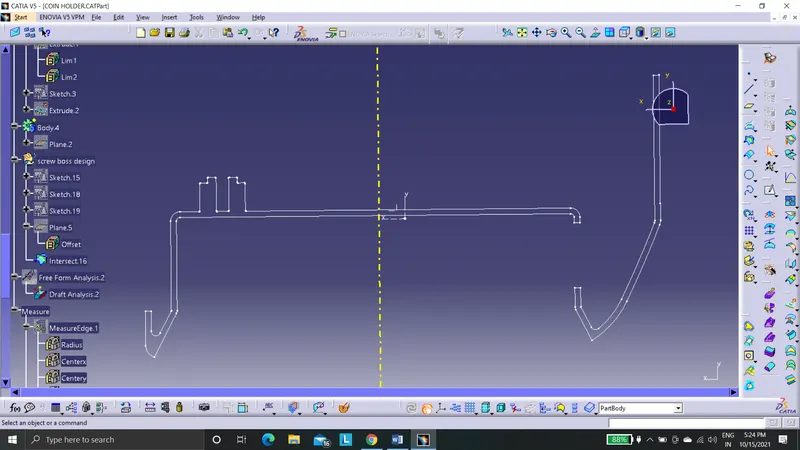
CROSS SECTION PROFILE OF SCREW BOSS
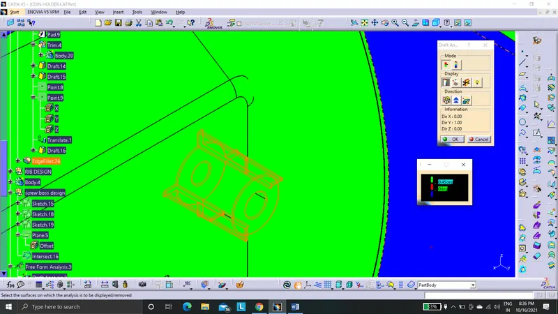
DRAFT ANALYSIS
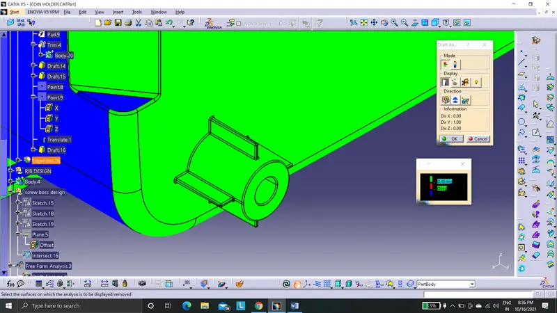
The darft analysis is taken along Y axis. This clearly showa us that tooling directio clears all faces in screw boss.
DOG HOUSE DESIGN RULES
- THICKNESS (W)
The dog house thickness at the junction with the class B surface should be 0.4 times the main wall thickness or less than that. This slight change in cross section assist in mold filling ability.
W = 0.4 * t mm
- FILLET RADIUS
Optimal fillet radius is 0.25mm. By smoothening the corners we can reduce presure drop and stress concentration problems.
- HEIGHT
The height of the contraction in dog house can be 3 to 6mm from B surface. The minimum height of dog house should be 6mm. Less than this height may reduce the strength.
4. WIDTH
The width of the dog house should have a minimal value of 12mm.
For steel width/height ratio is 3:1, prefered ratio is 2:1
5. DRAFT
The minimum draft for boss walls is +/-1.5 degrees.
DOG HOUSE DESIGN
- Importing the coin holder component into CATIA interface.
- Sketch a 20*20 square profile in the base surface.
- Do surface extrude on it. The minimum specified height is 6mm. we can take 21mm.
- Extract base surface, untrim it, extrapolate it and offset it by 20mm.
- Use trim command.
- Inset a new body.
- Thicken it.
From design rule,
The thickness at junction of B surface and dog house should be 0.4*t.
Therefore
Thickness at junction = 0.4 * t
= 0.4 * 2.5
= 1mm
We can take dog house thickness as 2mm.
- Extract the wall which is opposite to open side, untrim it, extrapolate it and offset it by 19mm.
- Trim the solid body.
- Draft is given of about 1.5 degrees along tooling direction Y and Z.
From design rule,
The minimum drat angle for boss is +/- 1.5 degrees.
- All the edges are given 0.25mm maximum fillet radius.
- Now we can create screw boss abd ribs on top of it.
- Sketch the boss profile in the base surface.
- Inset a new body.
- Pad the profile. Thicken it.
From design rule,
I am choosing a M6 bolt. Its major diameter will be 6mm. Tap drill size would be approximately 5.5mm
Outer diameter D = 2.4 * d
= 2.4 * 5.5
= 13.2mm
- Change the extruded height to 15mm
- Draft is given of about 0.5 degrees.
From design rule,
The minimum drat angle for boss is +/- 0.5 degrees.
- All the edges are given 0.25mm maximum fillet radius.
- Now we can create ribs on bosses to stiffen it.
- Extract the surface on which the rib is to be designed.
- Draw a line and extrude it to create a surface.
- Inset a new body
- Thicken the surface by 1mm.
From design rule,
W = 0.4 * t
= 0. * 2.5
= 1mm
- Change the extruded height to 12.5mm
From design rule,
H = 5 * t
= 5 * 2.5
= 12.5mm
- Draft is given of about 0.5 degrees.
From design rule,
The minimum drat angle for ribs is +/- 0.5 degrees.
- All the edges are given 0.25mm maximum fillet radius.
Now creating another rib spaced at 5mm.
From design rule,
As per 3:1 ratio
Height /Width = 3/1
Width = 12.5/3
Width = 4.166mm
That is approximately 5mm.
FRONT VIEW
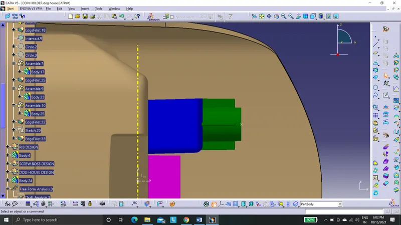
TOP VIEW
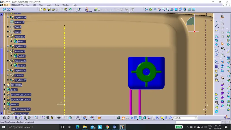
SIDE VIEW
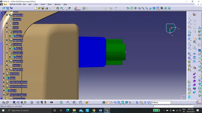
ISOMETRIC VIEW
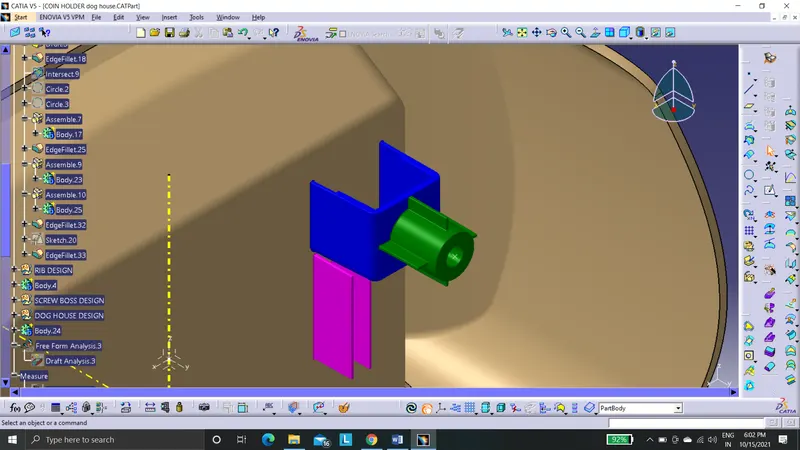
DRAFT ANALYSIS
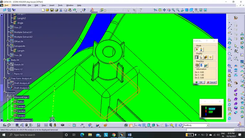
In which the draft analysis is done along Z direction. This toolling axis clears all faces in its direction. The given draft angle is 1.5 degrees.
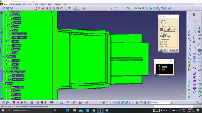
In which the draft analysis is done along Y direction. This toolling axis clears all faces in its direction. The given draft angle is 1.5 degrees.