Week 9 - Attachment Feature Creation - Challenge 2
Procedure To Design Screw Boss & Dog House for Coin Holder
Step -1: - to design the Screw Boss and Dog house on the Coin Holder insert a new geometrical set in the construction features and name as Screw Boss and define the Geometrical for sketching
Step -2: - in the geometrical set extract the coin holder bottom fact then insert a positioned sketch set with the vertical and horizontal axis in their position and start sketching in it. in my assumption, my screw diameter is 6mm for the tapping I left the 0.4mm thickness on both sides so the diameter of the hole is 5.2mm and the thickness of the hole is 0.6 x t of the main component for the hole we need to add the thickness on both sides and add with hole diameter, therefore (1.5 x 2 =3) and the final thickness of hole or outer dia is 5.2 + 3= 8.2mm
`therefore` 0.6 x 2.5=1.5mm
After sketching the 2 circles insert the body and go to the part workbench and use the Pad command for giving the screw boss height there is a formula for the height of screw boss
The height to diameter ratio = 3:1
`therefore` 3 X 5.2 =15.6MM
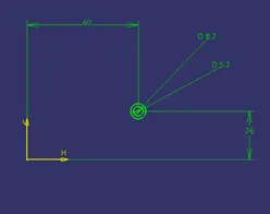
But in our case if we are taking the height is 15.6mm is not getting enough strength so I am taking the height of the component is 12mm
Note: - there are Guidelines for Design of Screw Boss
- Draft
- Thickness
- Height to Diameter Ratio
- Optional Radii
- Boss Gussets
- Coring Out Bottom
This is the points to be noted when design 0n Screw Boss.
Step -3: - use the pad command and enter the value of 12mm and in opposite direction take 1mm to merge with the component. And check the screw boss it satisfies the design parameters. And add the draft of 0.40 for the hole.
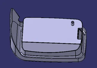
Step -4: - Add the ribs Or Gussets them to strengthen the screw Boss and start with the sketching of line by taking screw boss sketch as reference and draw the two connecting lines and give the 20mm length and exit the sketch and use pad command with the height of 10mm and add the thickness of 2mm from the neutral axis of the sketch and use the Boolean in operation and with union trim command and aspirate the inner lines that connects the hole. And add the Drafts for the gussets with 0.40 angle for the with the base of component
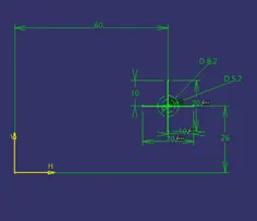
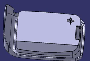
Make an intersection with the Screw Boss and check the parameters of the screw boss. The final gives the fillets for the screw boss of a minimum of 0.25 radius. And use the translation option to make the object move from the required position.
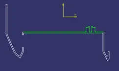
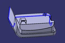
Step -5: - now start designing the Dog House for the component. The dog house is mainly used to avoid the sink marks on the component and to enlarge the extension of screw Boss up to certain heights.
Step -6: - to start the Dog House insert a geometrical set and name as Dog House and start with the point at the center of the hole and use the point and create a plane in that plane start sketch on it draw a rectangle with 12mm of length and hide one side of the rectangle. And extract the line for extract the line use sweep command in sweep tool use Draft with Direction option with an angle of 1.50 select the tooling axis is the direction of pull in inside if the dog house with 21mm length and use the base extract and make an offset of 20mm from the base and trim the extra surface
Step -7: - insert the Part Body and go to part design work-Bench and use thick surface command and add the thickness of 2mm on outside of sketch
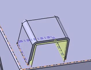
Step -8: - Deactivate the screw boss features and edit the Dog House to add the extra features like a C & B if any issues in deactivating the Screw boss try to solve the issues and create the C and B feature on the Dog House.
Step -9: - Before adding C and B Features check the Dog House is clearing the Tooling axis the main issue with the dog house it cannot clear the normal tooling axis of the component. we need to draw a Side Core Tooling axis for the Dog House. To create the side core tooling axis got the Tooling Axis geometrical set and select the line command and select the point in directions select the Z-axis in the direction of the line. Then give the Draft for the sides of the dog house and in the base keep the rare face for the axis of Draft select the side core tooling axis and check the draft is going to the component and select ok for the draft after giving the draft give the fillet for the dog house for inner face give the value of 1mm and for outer radius of the fillet is 1mm + thickness of component is 2mm= 3mm for the outer face
Step -10:- next process for the dog house is to add the C & B features for the C feature it was given as 40% of the main component thickness
`therefore`2.5 x 0.4=1mm
Take inner face as extract and make an offset of 1mm to outwards and for the B feature it the height can be taken as 3mm to 6mm in my case I am taking as 4mm and use cut with a surface command from the part-work bench and trim the inner part of the dog house and add draft for the cut top walls of the face at the draft value of 0.50 and at final add fillets for the final dog house
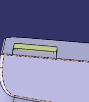
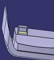
Step -11:- at the final step of the dog House move the screw Boss features on the top of the Dog House by using the translate option to add the same feature in the component make a copy of the component and use the translate option and fix the features where ever it required.
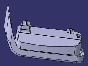
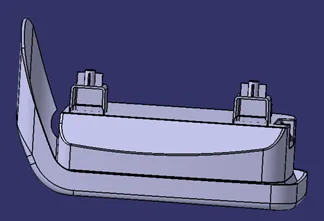
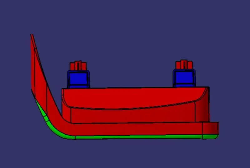
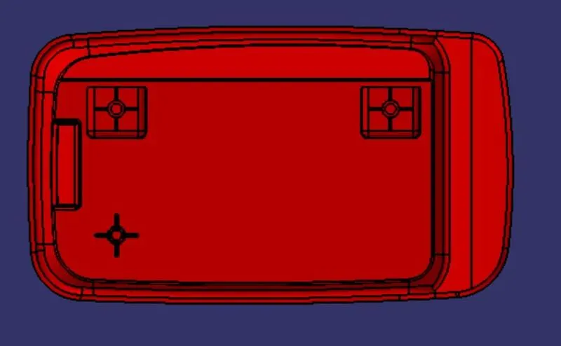
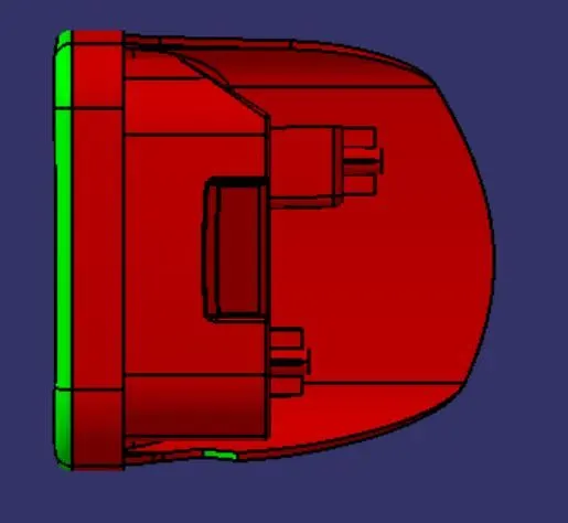
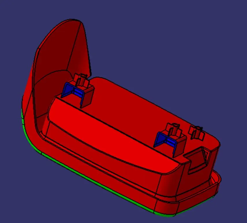
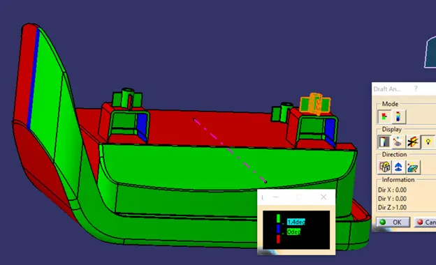
Step -12: - check the Draft analysis of the main component and Doghouse as well if there is any problem we can go to the previous step and rectify the problem. Draft analysis is also used to identify the problems in the component
For Draft, analysis select the Draft analysis tool in the Analysis command prompt the draft analysis tool opens and set the UCs icon lies on the Tooling axis and select the component and give an angle required for the component for the appearance of the component. Repeat the same process for the side core also
Coin Holder Tooling axis
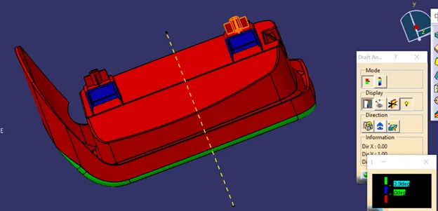
Side Core Draft Analysis
Images