Week 9 - Attachment Feature Creation - Challenge 2
Objective: To design the screw boss and dog house on the B-surface of the given component which is coin holder using Catia V5R21 with engineering standards.
Introduction:
Screw boss allows to create a means of connection between two components with the help of help of screw, and an additional support will be provided for the bosses by the ribs. There are few guidelines must be considered to design the screw boss.
General Guidelines for Bosses:
- Draft - 0.5 degrees on walls of boss.
- Thickness - Typically 40%* of the nominal wall at the base(t).
- Height to Diameter Ratio - 3:1.
- Radii - 0.25mm maximum radii.
These above guidelines must be followed to design the screw boss.
Dog house is also a engineering feature provided on the b-surfaces to eliminate the sink marks and also to assist the length issues to mate the components while using screwbosses.
General Guidelines for Dog house:
-
Doghouse wall thickness at the intersection of the part wall ( C ) should be 40% or less than the main wall stock ( T ).
-
Height of ( B ) should be between 3.0 – 6.0 mm.
Procedure for designing screw boss:
1. Open the given component and enter into the generative shape design workbench and use extract command to extract the base surface of the coin holder (select the class B-Surface).
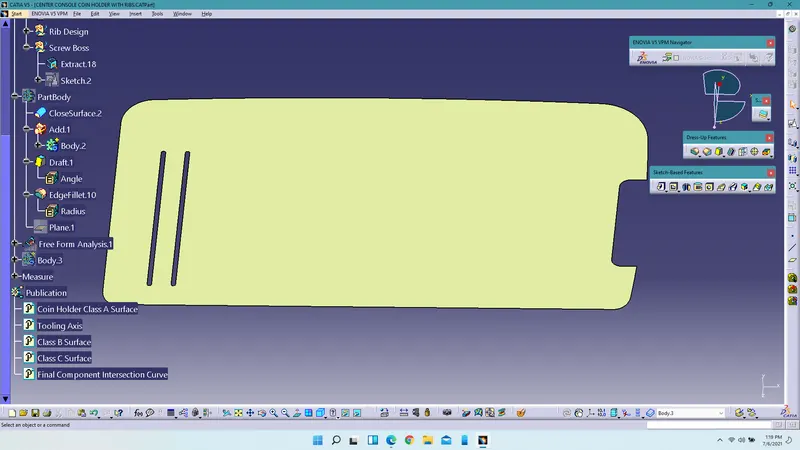
2. Create the sketch1 on the surface using positioned sketch command and draw two circles and constraint them. Make sure the sketch is Iso-constrained.
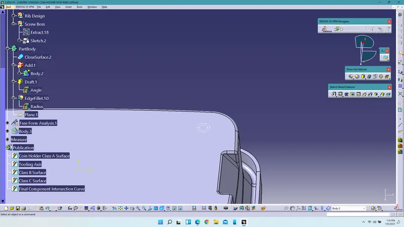
3. Create another sketch2 on the extracted surface and create the profile shown below.
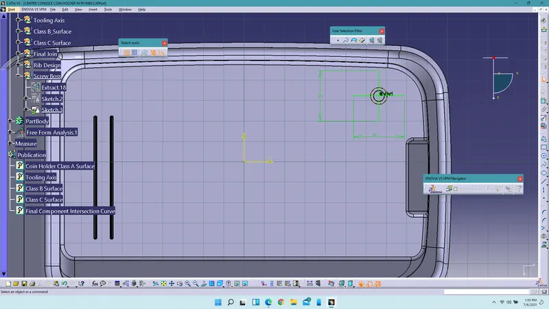
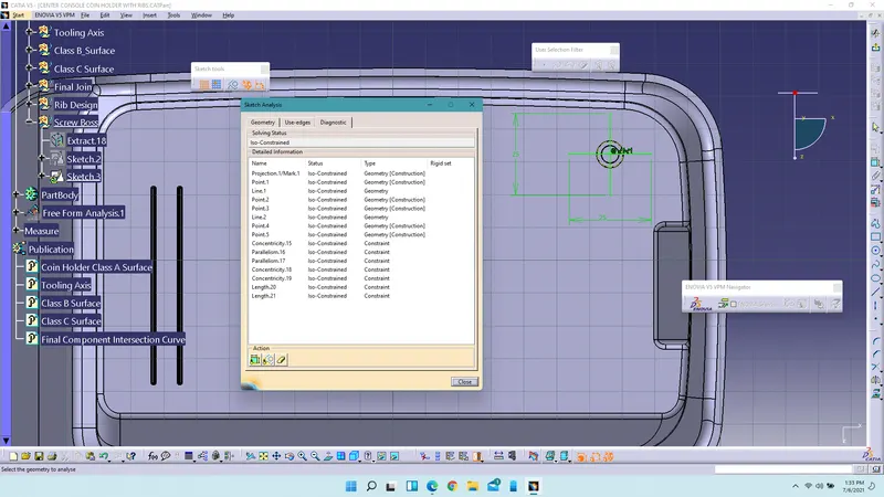
4. Enter into part design workbench insert a body and using pad command extrude the sketch1.
5. Insert another body and use pad command, by choosing thick option extrude the sketch2.
6. Use boolean operation which is union trim to remove the inside faces of the circle.
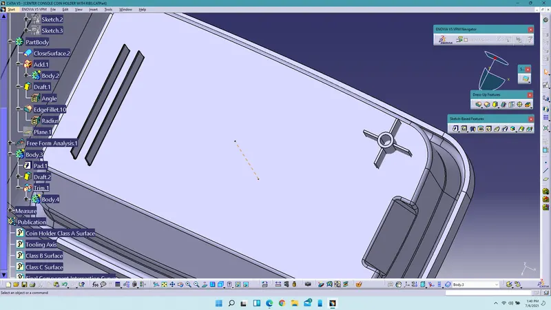
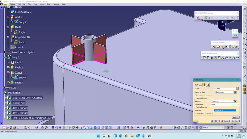
6. Use draft command to draft the faces of the screw boss. The minimum draft angle should be 0.5 deg. Provide the 0.5 deg draft angle for both extruded parts. Select the neutral element the extracted surface and pulling direction as tooling axis.
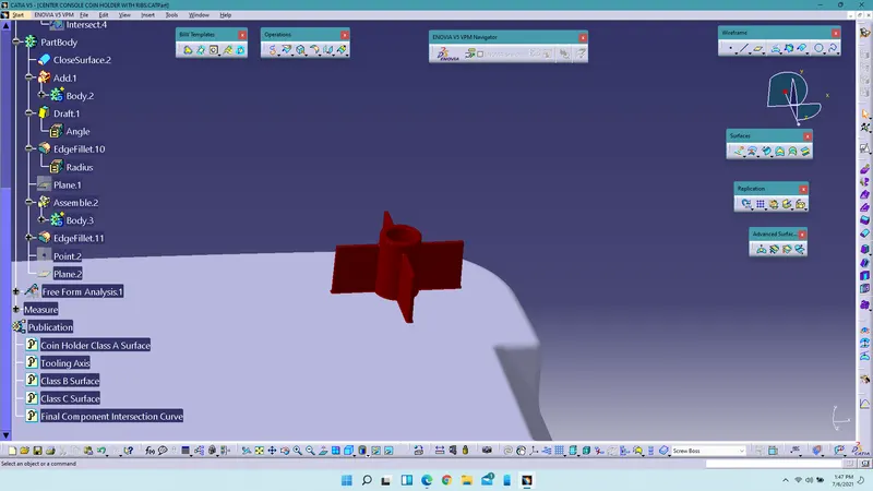
7. Apply fillets to the edges of the screw boss. In this case we will be providing 0.25mm as the radius.
8. Create a plane at the midpoint of the circle and provide the intersection curve.
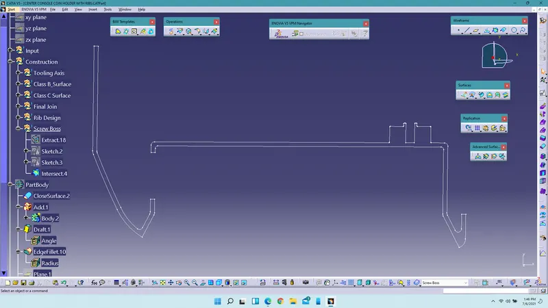
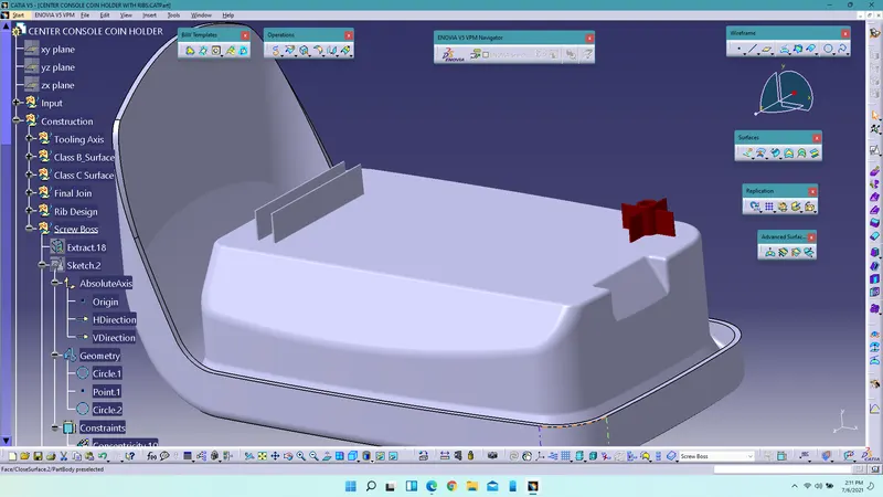
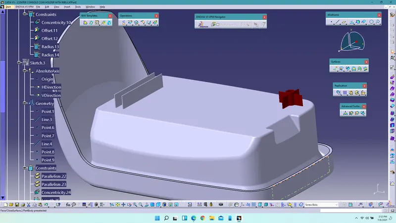
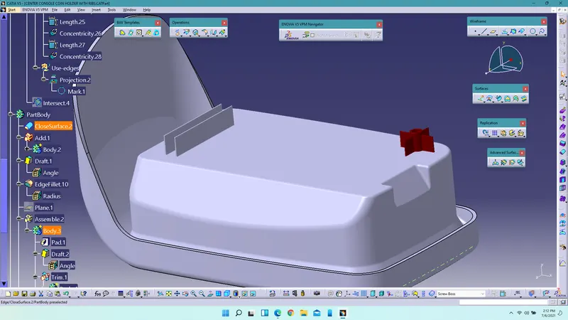
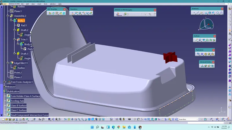
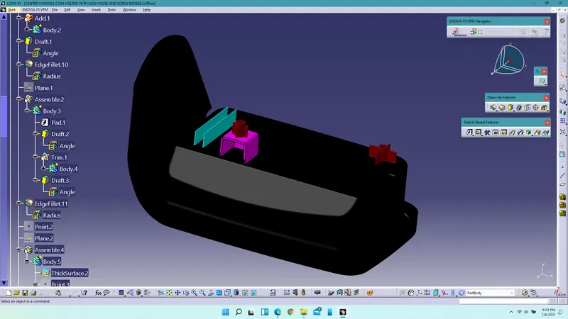
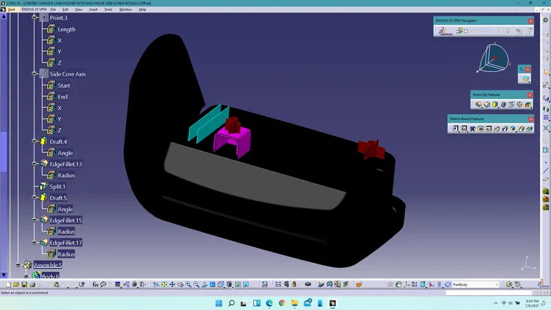
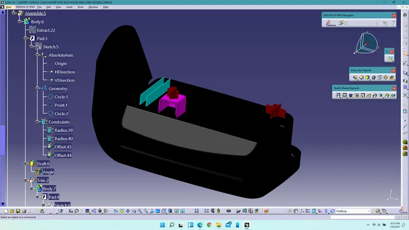
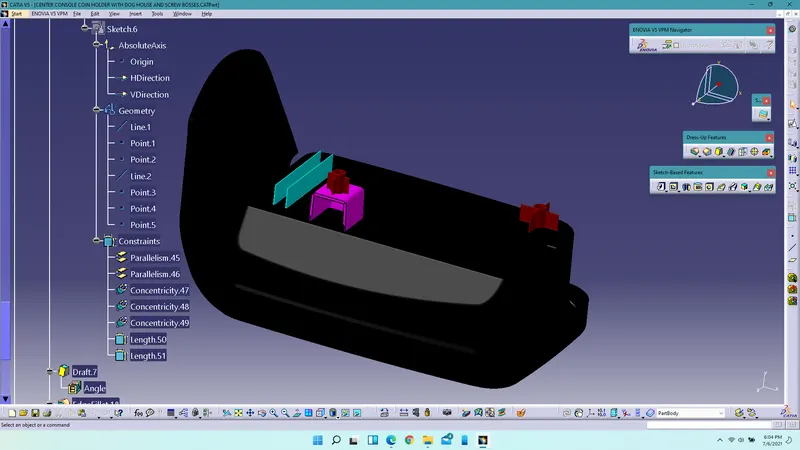
Feature Design Tree Of Screw Boss:
Procedure for designing dog house:
1. Extarct the A-surface and offset it to 1.5mm then untrim it and extrapolate it.
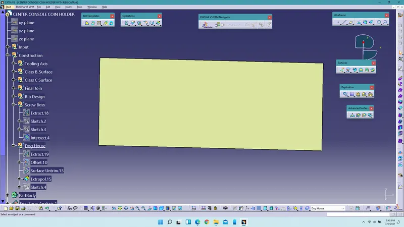
2. Create a sketch on the surface and make sure the sketch is Iso-constrained.
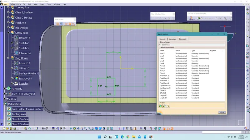
3. Use sweep command to extrude the sketch and provide draft angle as 1.5deg.
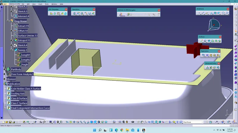
4. Using offset command offset the extracted surface to 20mm and use trim command to remove the excess surfaces.
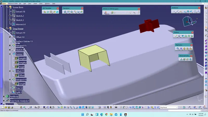
5. By entering into the part design workbench convert them into solids with the help of thick surfaces command.
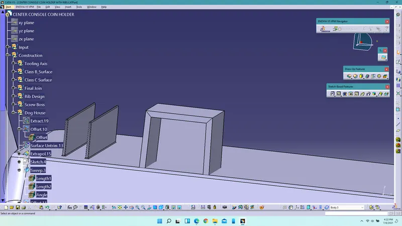
6. Create the side core axis and select the pulling direction as side core axis while providing 0.5 deg draft to the walls of the dog house.
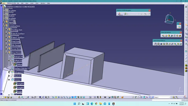
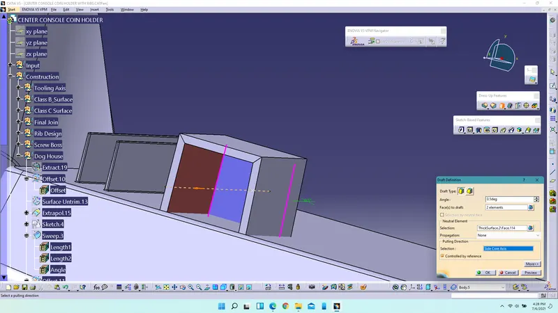
7. Provide fillets to the inner edges of the dog house.
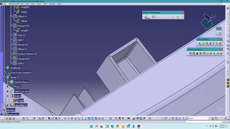
8. To create the bottom profile offset the extracted class A surface and using multiple extract, extract the inner faces of the dog house and extrapolate and obtain the required surface to create the bottom profile.
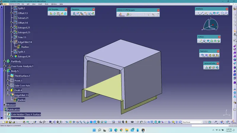
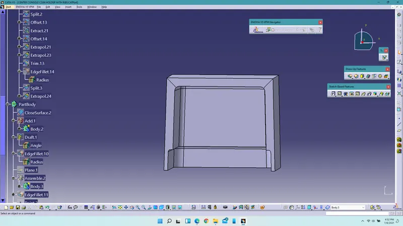
9. Split the surface and solids using split command in the part design workbench and create the profile.
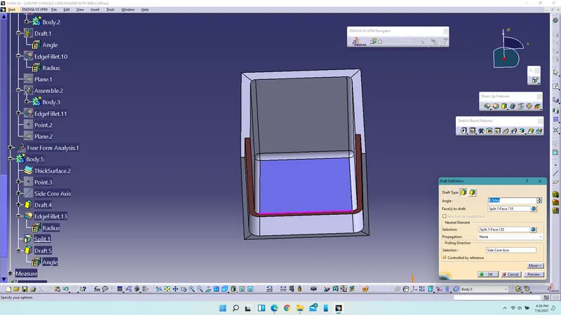
10. Draft the faces which are obtained during split command with pulling direction as side core axis.
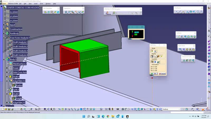
11. Perform draft analysis for the dog house using tooling axis and side core axis.
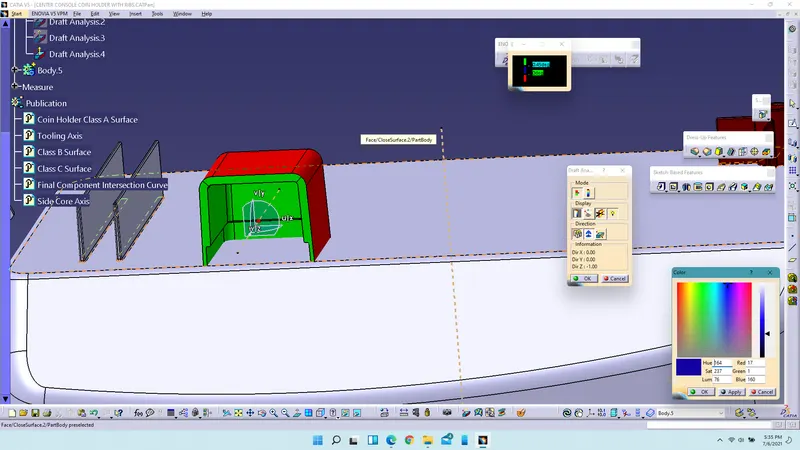
12. Assemble the dog house with the part body using assemble boolean operation command.
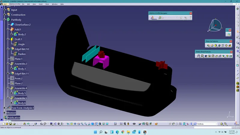
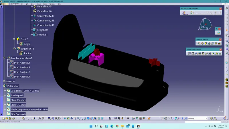
All the engineering features are provided on the B-surfaces and shown with differnet colors.
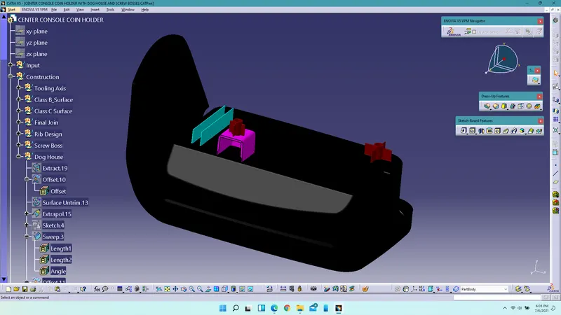
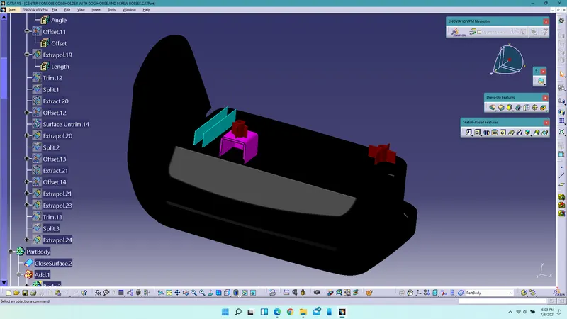
Feature Tree Diagram Of Dog House:
Conclusion: Both the screw bosses and dog house were designed with given considerations using Catia V5R21.