Week 9 - Attachment Feature Creation - Challenge 2
DESIGN OF THE DOOR TRIM WITH ENGINEERING FEATURES INCLUDES DOG HOUSE
AIM:To create the door trim component by generating the class B and class c surfaces with the aid of class A provided and cfreating the B side features include the ribs and the screwbosses by folowing the design parameters.
Procedure followed:
The following steps are included while designing the door handle with B side features
- Tooling axis creation
- Draft analysis of class A surface
- Class B surface generation
- class C surface generation
- Final trim
- Solid body generation
- Draft analysis of the solid body
- Dog house creation
- Translation
- Draft analysis of the B side features (Dog house)
Class A surface:
Class a surface is an asthetic surface with a polished surface which will be visible for the customers, and with the aid of the class A we could be able top geneate the class B and class C surfaces
Class B surface:
class B is an engineering surface where the B side features include the ribs, screw bosses , doghouses are located
Class C surface:
Class c is an intermediate surface between the class A and class B surfaces.It is generated by sweep feature either with reference surface or with the draft direction.If the generated C surface is parallel yo the tooling axis then we make the aid of the draft direction or else proceed with the reference surface
Commands deployed:
Surface commands:
- Extract
- Boundary
- Extrapolate
- Sweep
- Join
- Trim
- Intersect
- Multi section surface
- Surface extrude
- Multi extract
Part Workbench commands:
- solid surface
- Thicken
- Pad
- Draft
- Fillet
Tooling axis creation:
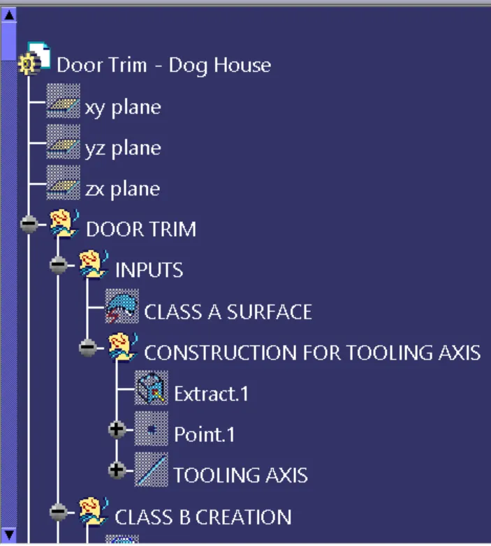
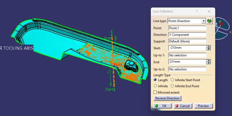
Orient the class a surface in various views and opt the best view to manufacture the part in a single go. Then extract the surface out from the class A surface and create a point at the mid point of the extracted surface and create a line in the view direction. and mark it as the tooling axis
Draft analysis of the class A surface :
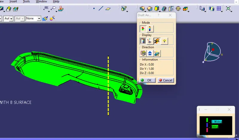
Now perform the draft analysid onthe class a surface withn the aid of the tooling axis created, and check whether all the class a surfaces are clearing with the draft or not or else there may be two possibilites either to change the tooling axis position or else we need to come to an conclude that there might be an issue persists in the class A surface and it need to be modified . so we need to continue irrespective of the minor issues
Class B surface creation:
Once the draft analysis is satisfactory then we need to move to the class B surface creation First of all offset the class A to 2.5mm so the offset sutrface should be beneath the class A surface
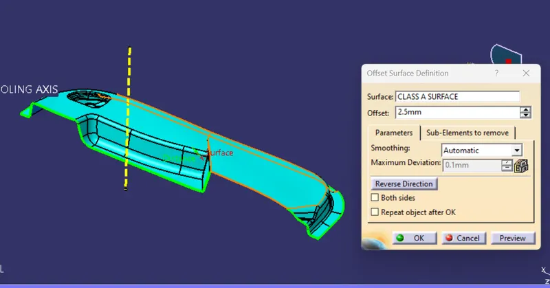
so the obtained offset surface be like
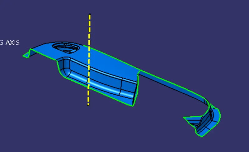
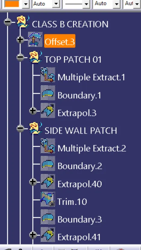
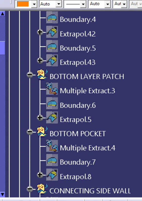
So now we need to work on the patches divide the class a surafce into 5 individual patches excluding the fillets and deloy the sufficient surface workbench features to form the proper class B surafce and last apply the fillets and thus formed B surafce be like
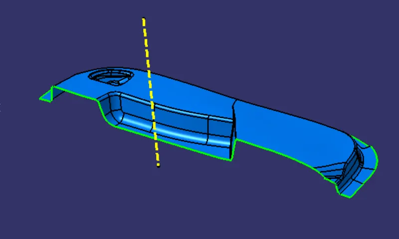
Class c surface creation:
In case of class C surface creation we need to follow 2 rules if the created class C surface is parallel to the tooling axis direction then we use the sweep with respect the draft direction and provide a draft of 3 degrees or else we need to use the reference surface sweep .Now create the C surface patch by patch rather than create it on a single go as we might encounter lot of issues at the end .so create a boundary of a small patch and swwp it either by using draft direction or by reference surface . Generally fillets create problem while generating the class c surafce rather than of using the sweep we deploy the multi section surface feature by creating a spline and using the guide paths as the two adjacent sweep edges.
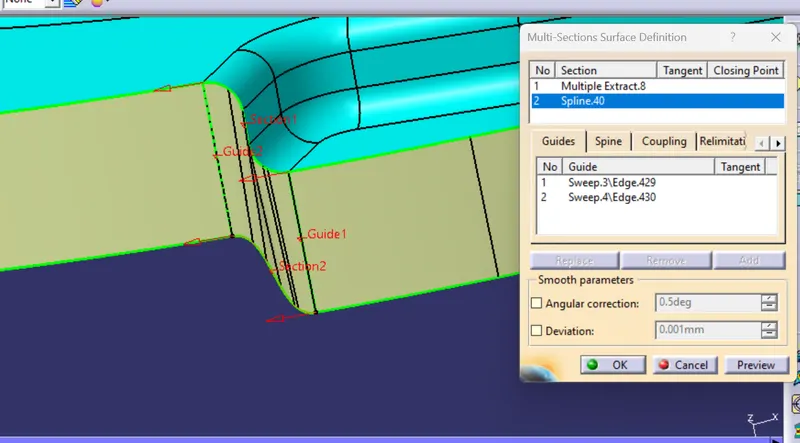
After all extrapolate the surface so that proper intersection happens then trim the surfaces togther and join the surface to a single surfae by using the join command
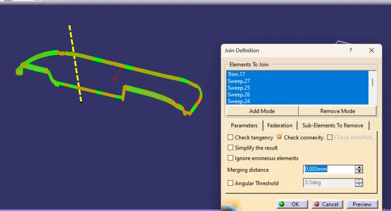
So the maximum merging distance would be 0.003mm
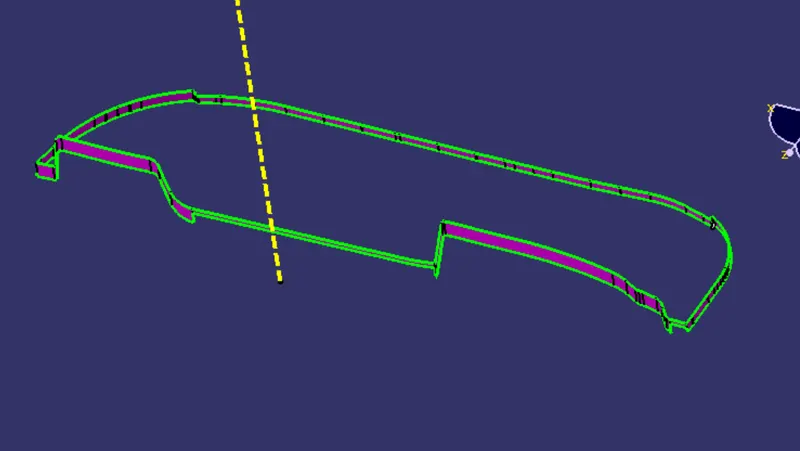
This is the class c surface . Now join the class a and Class c surface together with join command
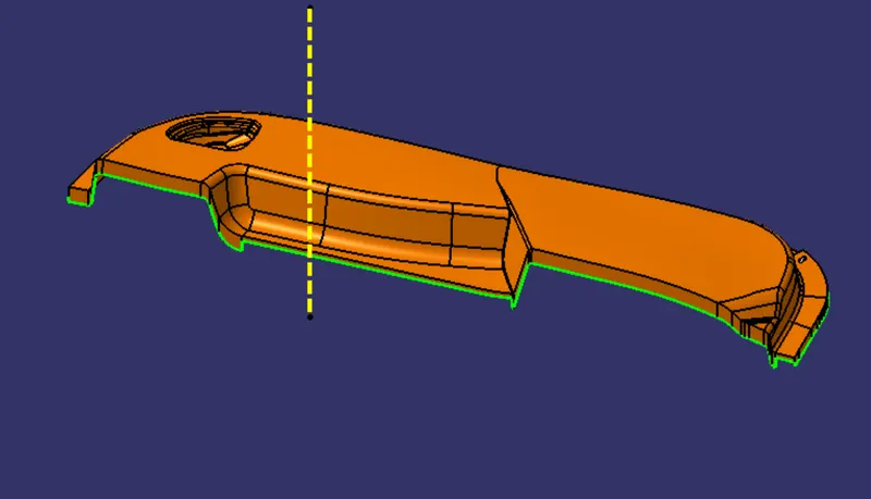
Final Trim:
Now the trim the join of class A and class C surafces with the class B surface before that ensure that both the surfaces are intersecting properly with each other otherwise extrapolte to a minimum distane to form a proper intersection then after trim we obtain the final surface with a thickness of 2.5mm
First check for the intersection between two surfaces
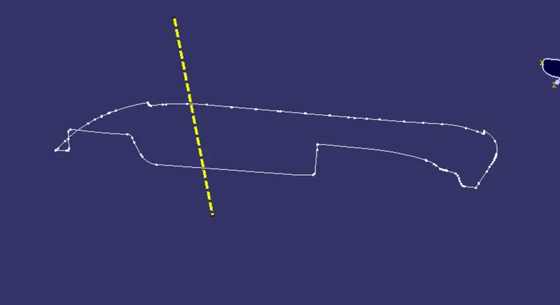
Be sure to check whether there might be any black dots in the intersection as they represent the open surfaces if else continue to the final trim or else work for the proper intersection
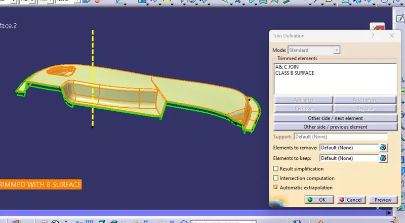
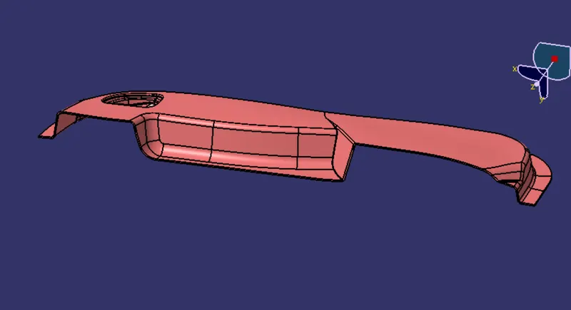
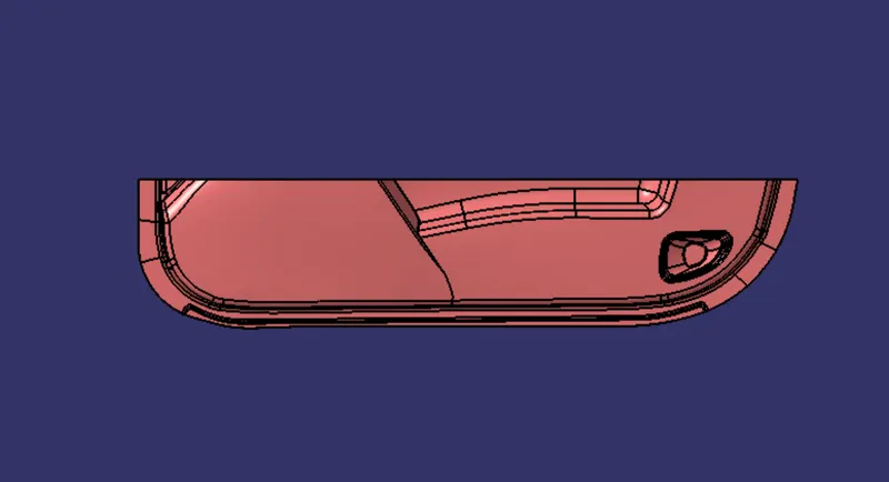
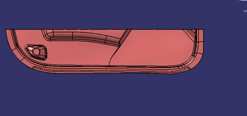
Now the final surface component be
Solid body creation:
Now insert a new body and go to the part workbench and apply the soild surface feature to generate the solid body
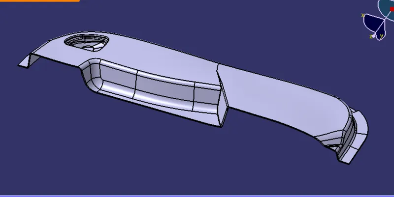
Noiw perform the draft analysis on the sold body to check whether all my surfaces which the draft is provided are clearing the draft or not as if the draft is not provided , during ejecting the component from the core and the cavity thesurface edges got detorated and surface finish will got damage so we need to provide a draft of 3 degress
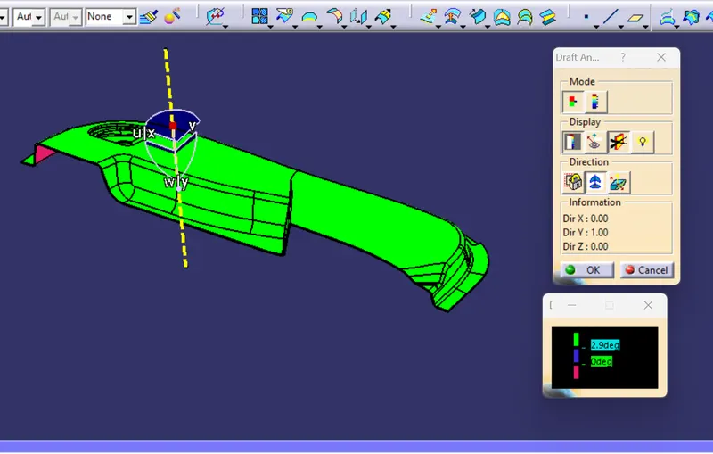
Almost all my surfaces got clearing the draft analysis and some surfaces cant be able to clear the draft analysis as they might have some issues in the class a surface . So proceed with the B side features creation og dog house
Dog houce creation:
Dog house is an engineering feature used in the plastic trim design. Dog houses are used as supporting features. Sometimes other engineering features like snaps; locators, etc. are mounded on them to increase their strength. Dog house and other engineering Features are built on B-surface.
Design rules for Dog house creation
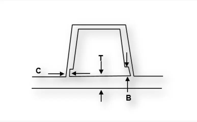
"C" is where the doghouse contacts the backside of the surface
Doghouse wall thickness at the intersection of the part wall ( C ) should be 40% or less than the main wall stock ( T ).
The height of ( B ) should be between 3.0 – 6.0 mm
Dog house design procedure by considering the design rules:
Extract the surface on which we want to create the dog house and create a sketch on a plane
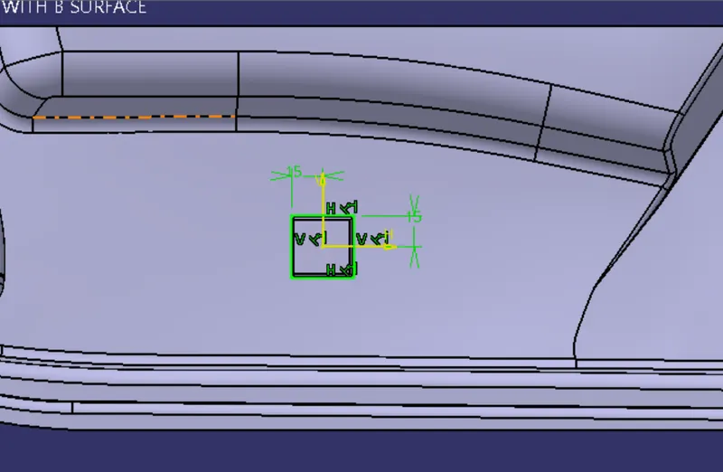
Now pad the sketch to a distance not greater than 50mm and apply pad in the bottom direction too so that proper trim can be possible with the main part body .during padding the refernce direction of the sketch should follow the tooling axis
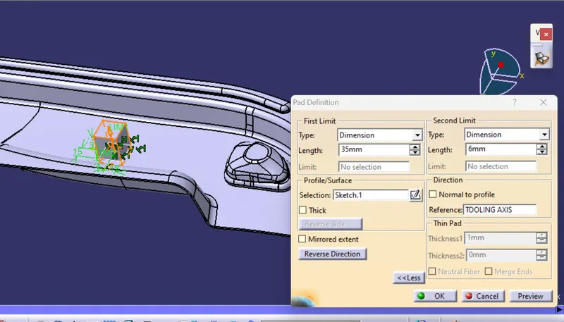
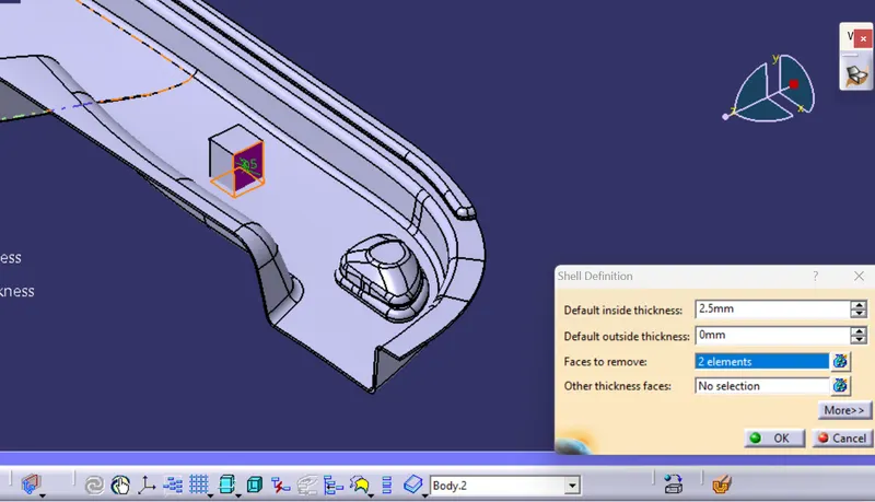
Now apply the shell feature to an inside thickness of 2.5mm
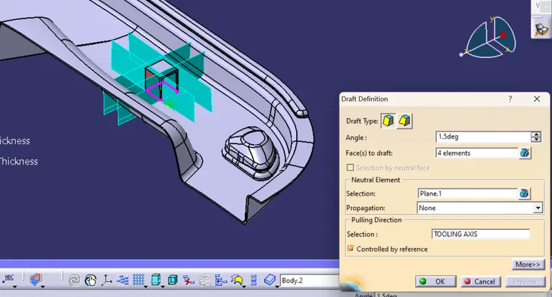
Now apply the draft on the outer sides withna draft angle of 1.5 degrees
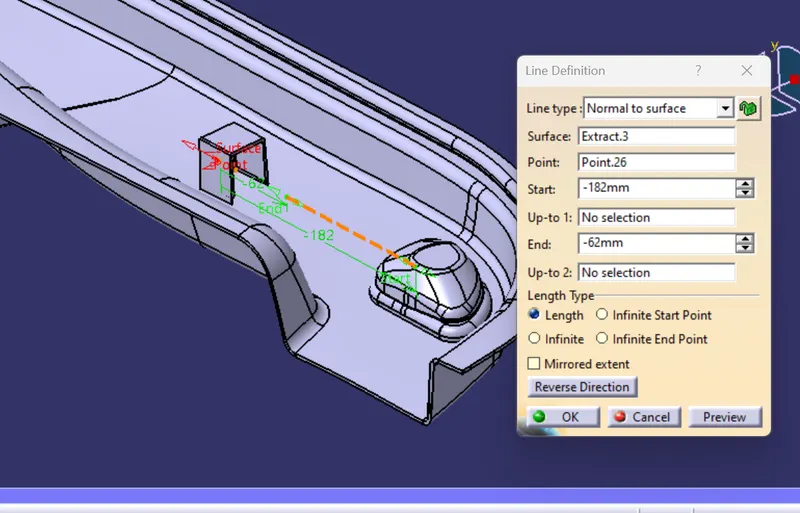
For applying the draft on the inner surfaces we need the aid of the side tooling axis
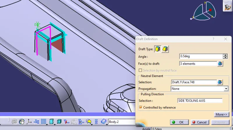
Now apply the draft to the inner surfaces to an angle of 0.5 degrees
Now create the coring for the dog house as the corimg can eliminate the sink marks formation
Use the pocket feature to create the coring
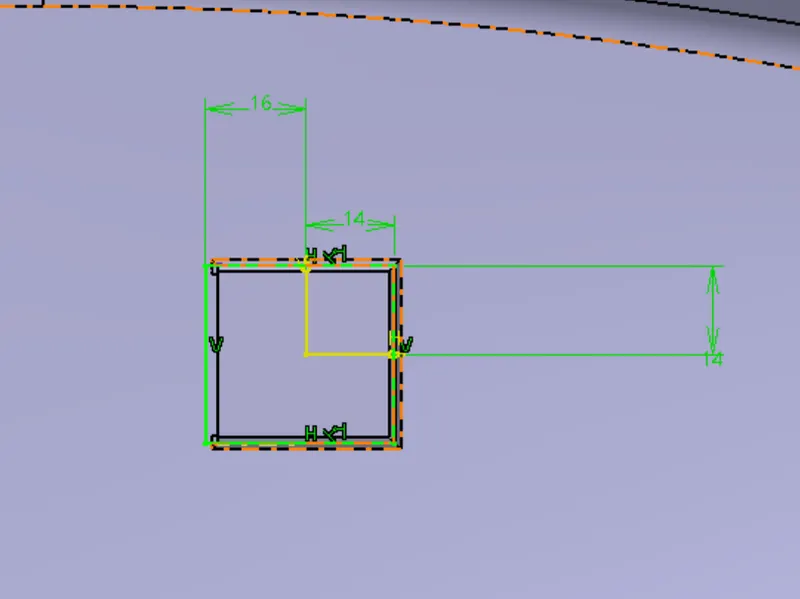
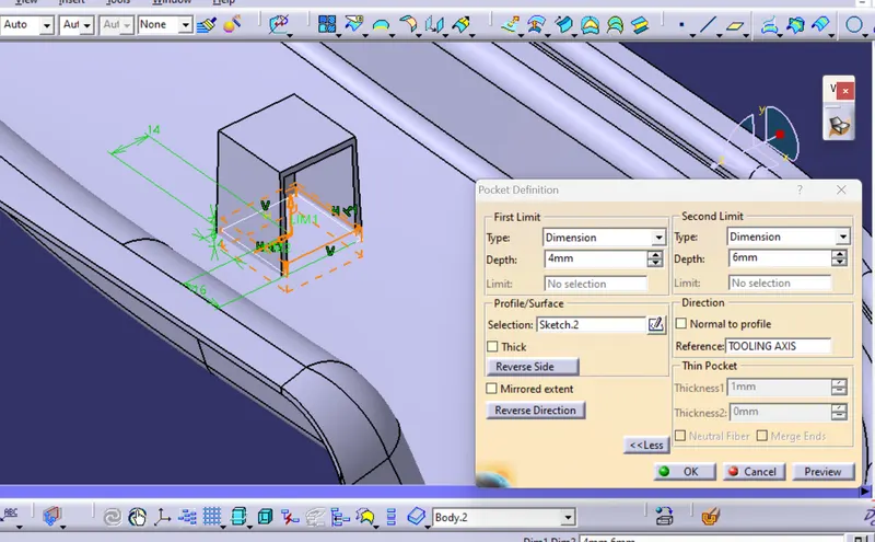
Now apply the draft of 0.5 degrees to the coring edges too
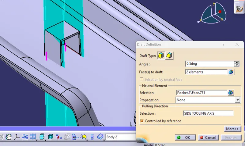
Now apply the requirred filletes of 1 mm on the outer edges and 0.5 mm fillet on the inside edges
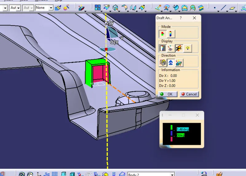
Now perfor the draft analysis for the dog house
.
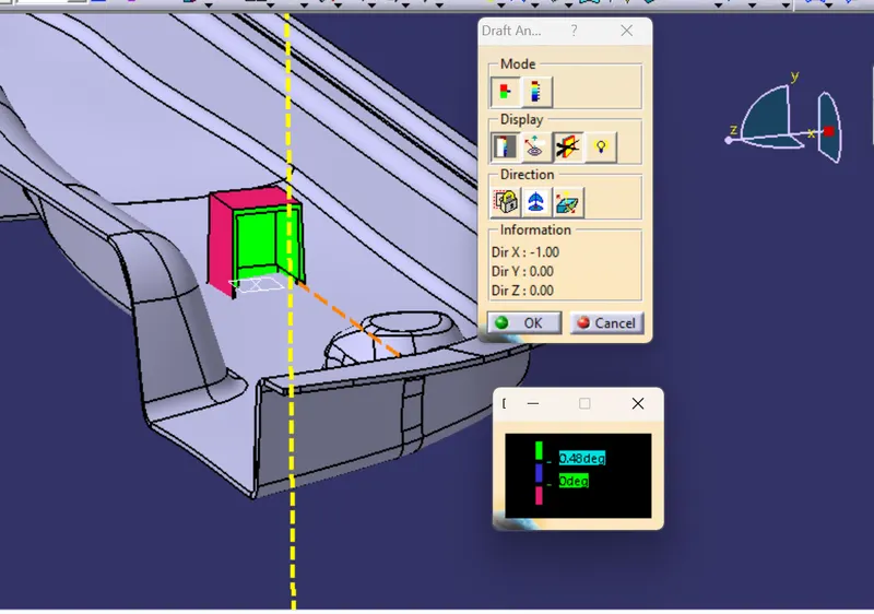
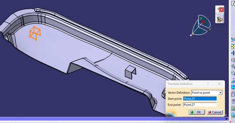
Now use the translate feature to create the dog house at different positions First of all create a new part body and copy the dog house features and paste special in the new body with a link and translate the body at different positions using point to point translate
VIEWS:
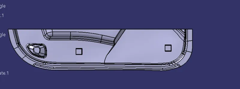
ISOMETRIC VIEW
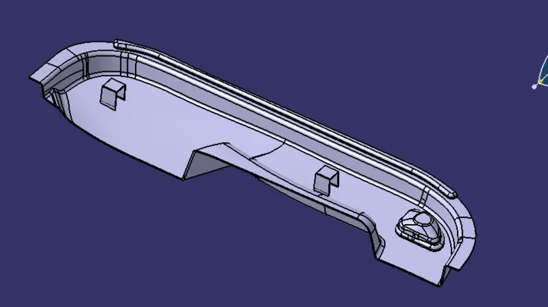
FRONT VIEW
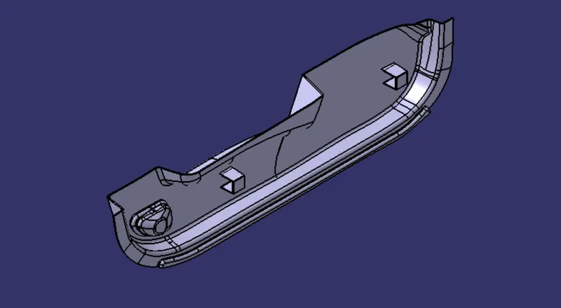
BOTTOM VIEW
Conclusion:
Hence the door trim with dog house feature is created by following the design rules and proper draft analysis is performed and final component is obtained
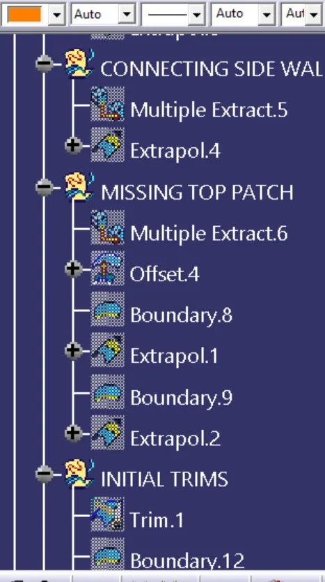
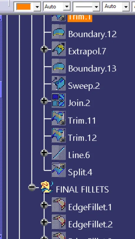
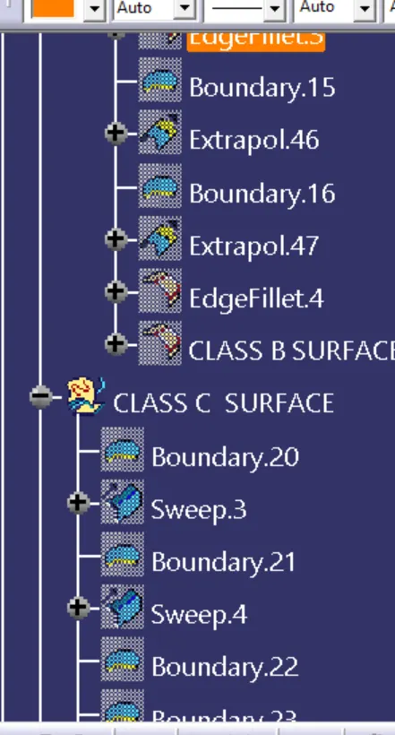
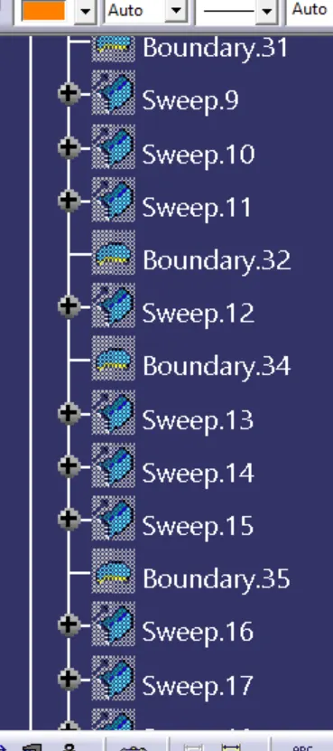
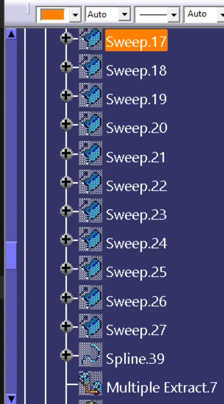
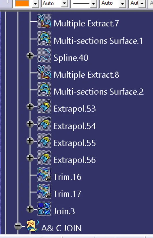
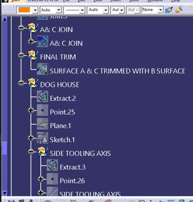
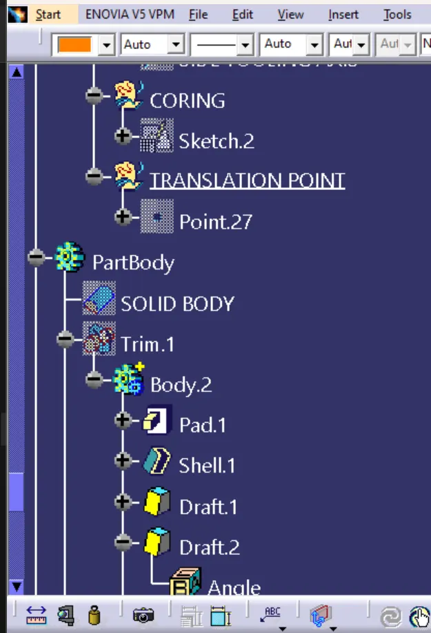
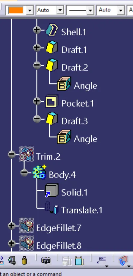
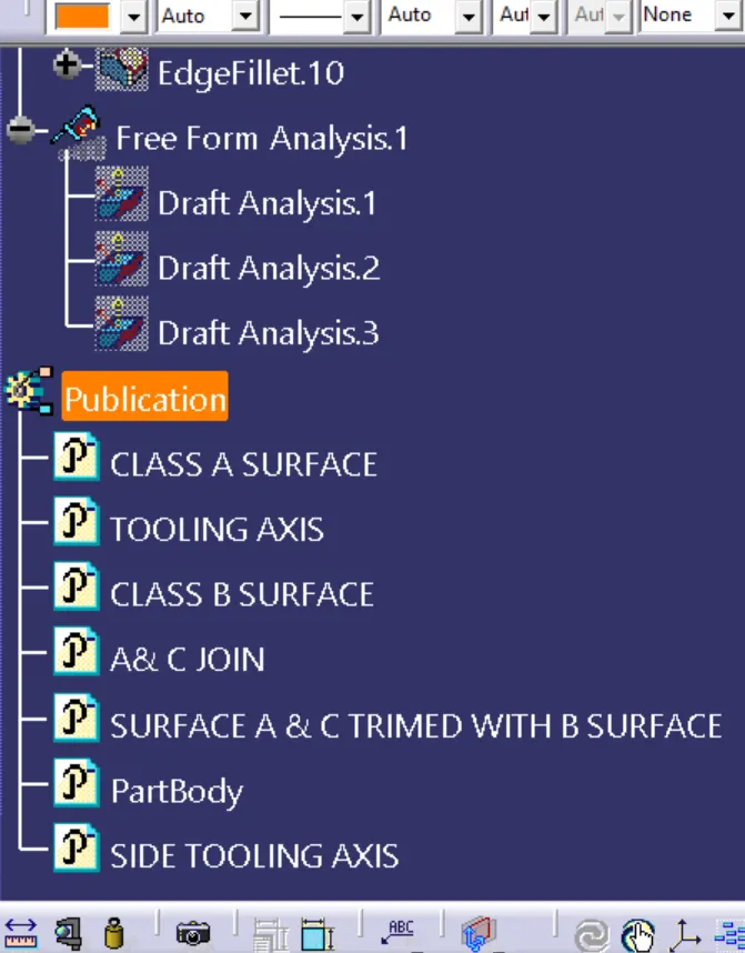
Tree structure: