Week 9 - Attachment Feature Creation - Challenge 2
OBJECT :
Design the Dog House for the Door Trim considering the design rules design rules in given class A surface analysis and draft analysis on the final component.
TOOLING AXIS CREATION:
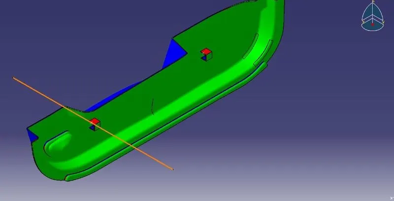
Tooling axis is which side to perform core and cavity direction to finding easily when a take a any surface to extract and create point on that surface and take a line that point (point-direction) select required direction.
CLASS A SURFACE:
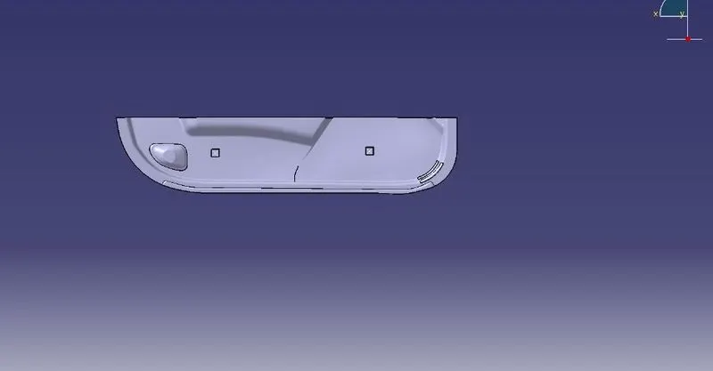
In Automotive design, a Class A Surface in any of a set of freeform surfaces of high efficiency and quality. Although, strictly, its nothing kore than saying the surfaces have curvature and tangency alignment- to ideal aesthetical reflection quality.
B SURFACE CREATION:
- Extract the surfaces from the class A using multiple extract and untrim them.
- Use Extrapolate to make sure that all the untrims are properly intersected to trim and offset the surfaces to 2.5 mm to create the thickness.
- Trim the extra surfaces using trim command.
- Insert them into new geometrical set and name it with respective part names.
C SURFACE CREATION:
- Extract the boundary from the class A surface using boundary command.
- Using disassemble tool to divide the boundary as the boundary contains domains.
- Use sweep command to produce c surface
- by using boundary and surface with respect to angle 3 degree or 93 degree
DOG HOUSE:
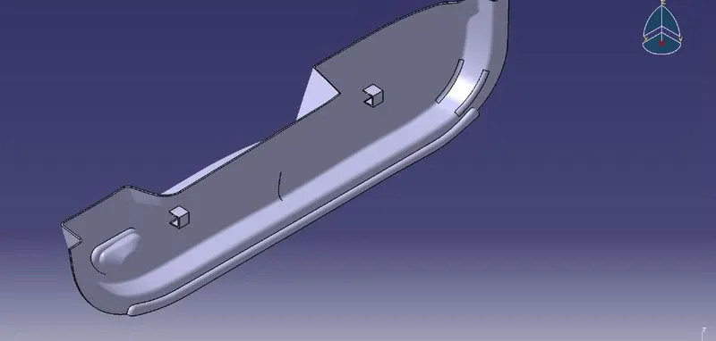
Create the Dog House as per the design rules and give the requiredd draft angle.
- Dog House wall thickness at intersecton of the part Wall(C) should be 40% or less than the main wall stock(T).
- Height of (B) should be between 3-6 mm.
DRAFT ANALYSIS:
Align the compass and click on the surface and as expected the model is mostly in red color i.e. negative draft with respect to the axis. whenever draft analysis is mainly for find the designed part should be produceble or any difficulty will be faced in manufacturing plants
CONCLUSION:
- The Door Trim Dog House Plastic Part Component using the Class 'A' surface are Created.
- The Tooling axis for a class 'A' Surface, which meeting the requirement of the draft angle are analysed and perfrmed.
- The solid model from the surface are created by using the Closed Surface Feature.
- To create a Attachement features Ribs and Screw Bosses on the created Class B Surface.
- The detailed report which explains the Draft analysis and Tooling Axis cration and colour scale varient are explained.
- The Class A, B and C surfaces are Published using the publication option.
- The expanded Tree Structure for the Geometrical Sets are explored .
- The expanded tree structure for part design are explored.
- The 3D part Model with various orientations are attached.