Week 9 - Attachment Feature Creation - Challenge 2
Week 9 - Attachment Feature Creation - Challenge 2
Dog House
Create the Dog House for the Door Trim considering the design rules mentioned in the video. Consider the thickness of the part to be 2.5 mm.
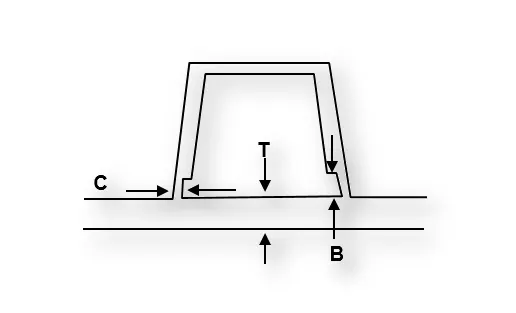
"C" is where the doghouse contacts the backside of the surface
-
Doghouse wall thickness at the intersection of the part wall ( C ) should be 40% or less than the main wall stock ( T ).
-
The height of ( B ) should be between 3.0 – 6.0 mm
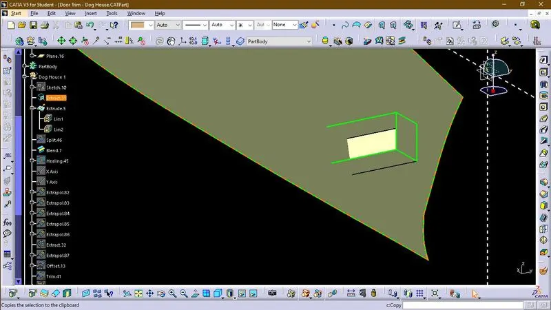
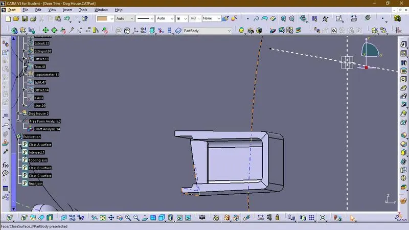
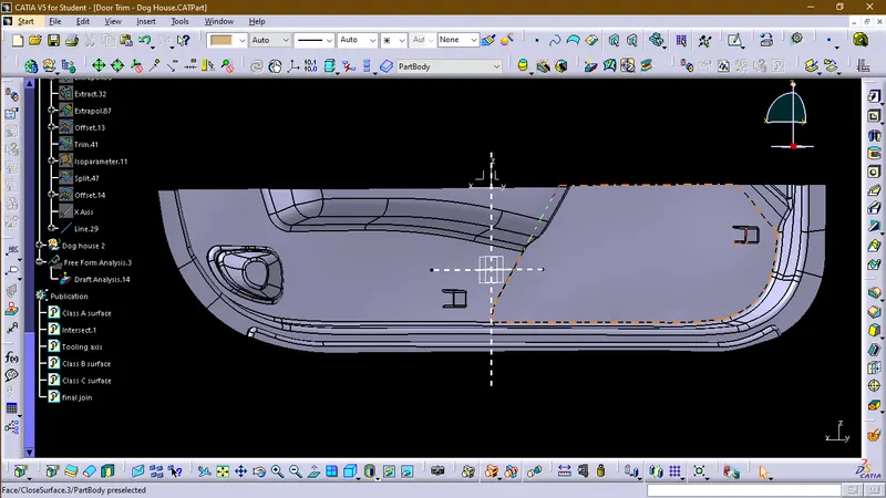
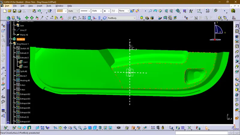
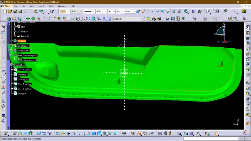
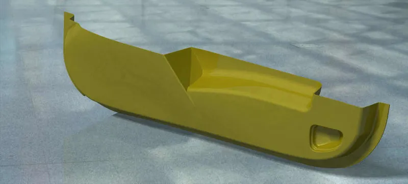
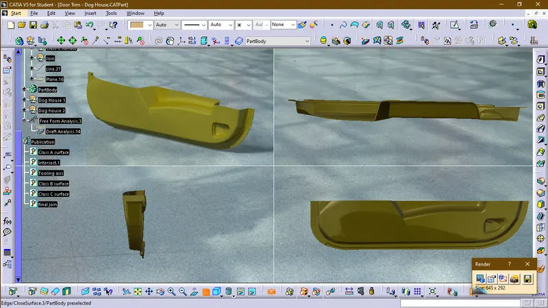
Following is the image of the part file on which we have to create attachment features.
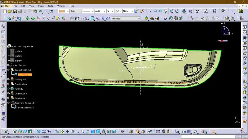
As the part file is a class A surface, therefore, we first have to create a solid part with the help of Class A.
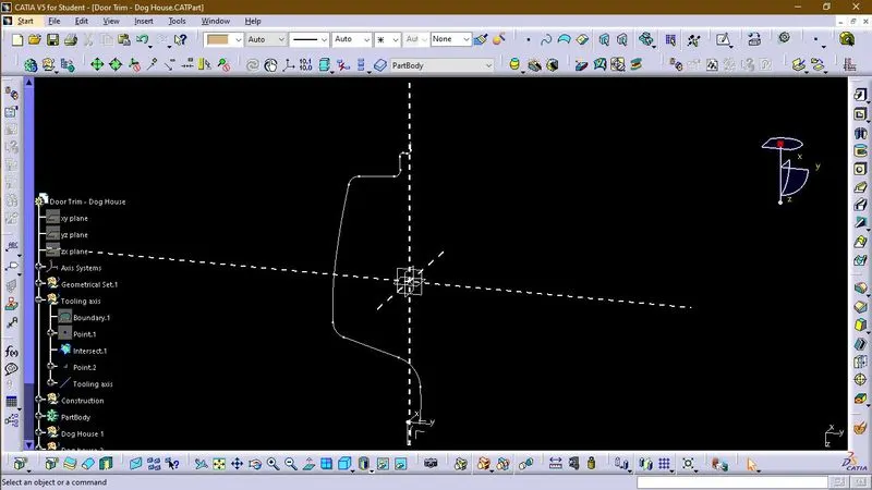
First, we create a tooling axis using the intersection method.
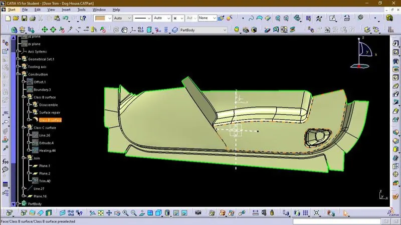
Now we created a Class B surface by using the following tools:-
1. Extract
2. Disassemble
3. Untrim
4. Extrapolate
5. Trim
6. Split
Then we created a Class C surface by using the sweep tool
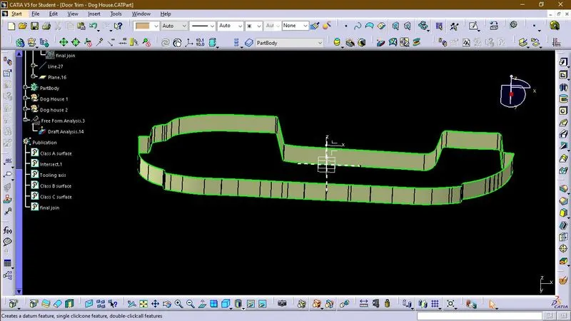
Then we joined Class A, Class B, and Class C surfaces
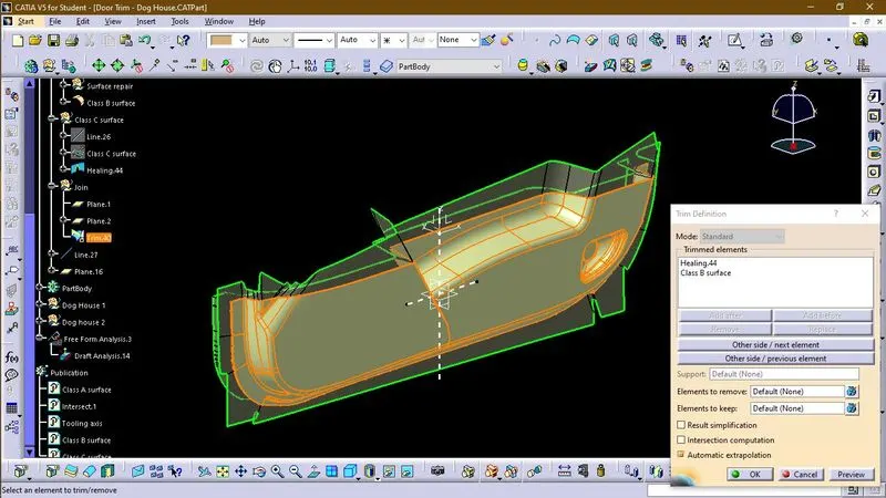
Dog House
The dog house is an engineering feature used in the plastic trim design. Dog houses are used as supporting features. Sometimes other engineering features like snaps; locators, etc. are mounded on them to increase their strength. Dog houses are subjected to draft analysis to prevent breakage of the component during ejection from the mold cavity. Dog house and other engineering components are built on B-surface.
DESIGN CONSIDERATION FOR PLASTICS:
1. WALL THICKNESS:
Thick sections waste material and are simply uneconomic. So solid shapes that would do the job well in wood or metal must be transformed to a 'shell' form in plastics. This is done by hollowing out or 'coring' thick parts so you are left with a component that regardless of complexity is composed essentially of relatively thin walls joined by curves, angles, corners, ribs, steps, and offsets. As far as possible, all these walls should be the same thickness. The Wall thickness guide range is 0.75 mm to 3 mm for reinforced materials and 0.5 mm to 5 mm for unreinforced materials.
|
WALL THICKNESS(W) =0.70*(NOMINAL THICKNESS OF PLASTIC MATERIAL) |
2. CORNER RADII
Properly designed corners will make a big difference to the quality, strength, and dimensional accuracy of molding. But there is another benefit too. Smooth curved corners help plastic flow in the mold by reducing pressure drops in the cavity and minimizing flow-front break-up. Internal radii should be at least 0.5 and preferably 0.6 to 0.75 times the wall thickness.
|
CORNER RADII= (0.6-0.75) * (NOMINAL THICKNESS OF PLASTIC MATERIAL) |
3. DRAFT ANGLE:
Tooling must be cleared for easy ejection of the component, from the core cavity. In order to clear tooling certain value of draft is given to the component. Minimum of 2-3deg is provided on all plastic components.
|
DRAFT ANGLE=2-3 DEGREE |
4. FILLETS:
|
Fillet on the inner side = 0.25 * Thickness of the plastic material Fillet on the outer side = 1.25 * Thickness of the plastic material Fillet on the coring edges = 0.25 * Thickness of the plastic material Coring thickness = 0.40 * Thickness of the plastic material |