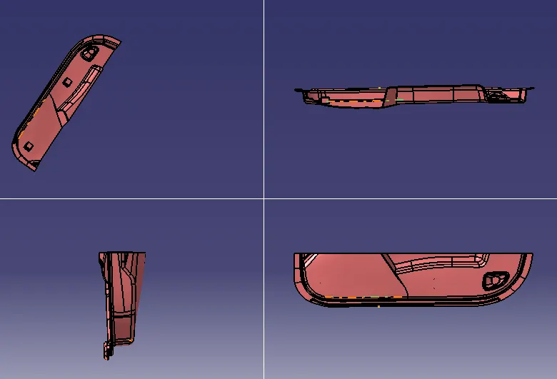
Week 9 - Attachment Feature Creation - Challenge 2
AIM - Create the Dog House for the Door Trim
CLASS A SURFACE
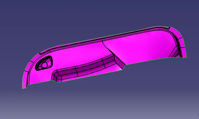
STEP 1 - Check the connectivity/continuity of the surface using the boundary tool or the close surface tool.
STEP 2 - TOOLING AXIS
- Check the best tooling direction by visualy considering the cost factor in mind. Here the best tooling direction is y direction because other two direction are problem making surafces.
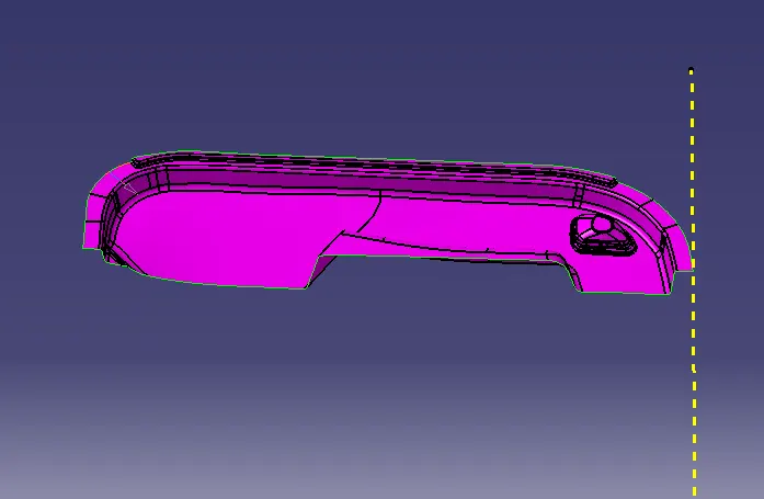
STEP 3 - DRAFT ANALYSIS OF CLASS A
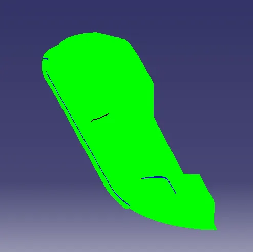
- Here the given class A surface is subjected to the daft analysis with draft angle 3 degree.
- From insert the draft analysis tool is taken, here we placing the compass to the tooling axis.
- Click on the class A, then we get a green colour on top and blue in the bottom. It means that draft angle decreasing from 3 degree to 0 degree.
- But some areas isnot cleared using the draft angle it shows the blue colour.
STEP 4 -CLASS B SURFACE
- Creating B surface by offsetting the surfaces from class A ,then Untrim and Extrapolate.
- Offset the component to 2.5 mm
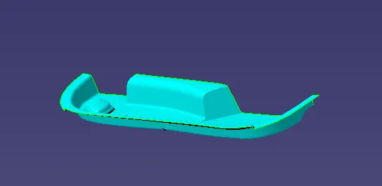
STEP 5 - CLASS C SURFACE
- Using the boundary and sweep command we got the Class C surface.
- Sweep command is use with the reference surface
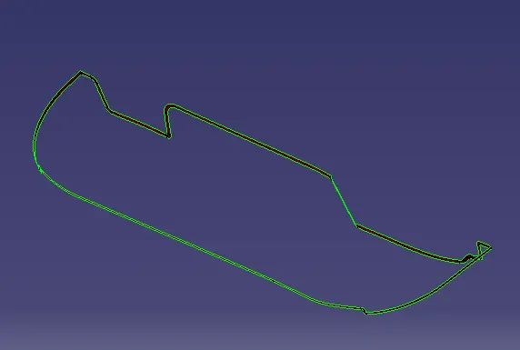
STEP 6 - CLASS A +CLASS C
- Join the class A and class C
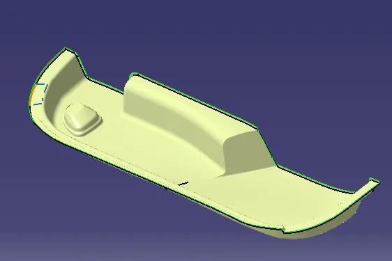
STEP 7 - DOOR TRIM
- Trim the joined part with class B surface we get the Door TRIM surface.
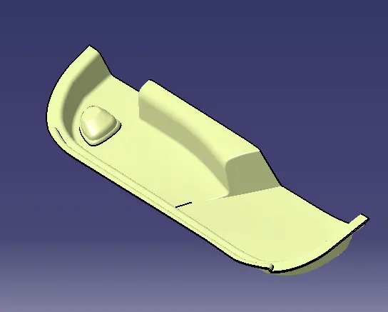
STEP 8 - DOG HOUSE CREATION
- Convert the Door Trim to the part using the Close surface tool in part workbench.
- B SIDE FEATURE CREATION
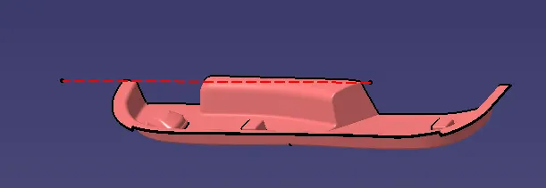
- FOR B Side feature creation we need both Tooling axis and Side core axis.
- The side core axis is created in the X direction.
SIDE CORE AXIS
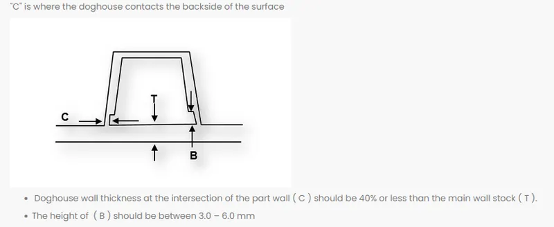
- Using the design rule draw the sketch for dog house
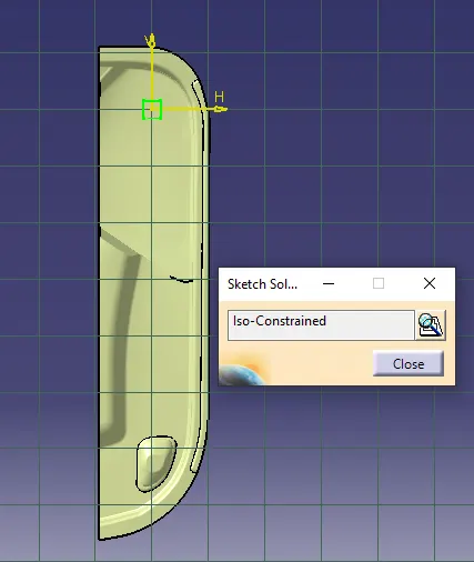
DOG HOUSE 1 SKETCH
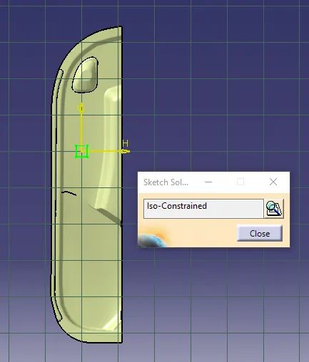
DOG HOUSE 2 SKETCH
- Using the commands like Sweep,Extract,Plane,offset,Extrapolate,Trim,Split etc.. ,we create the doghouses.
- Then the dog house draft analysis is done using the draft analysis tool. Here the analysis is cleared using the 5 degree draft angle.
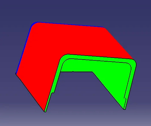
- After the draft analysis the Dog House is assembled to the Door Trim part.
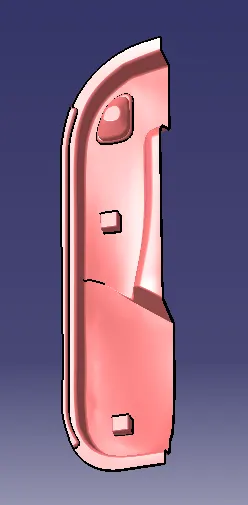
STEP 9 - DRAFT ANALYSIS OF ASSEMBLED PART
- The assembled part is analysed using the 3 degree draft angle.Here we seen that the dog house area is not cleared by the 3 degree draft analysis.
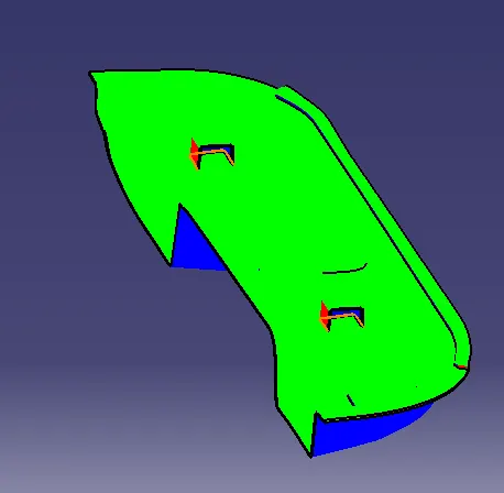
- Result of draft analysis with draft angle 0.5 degree.
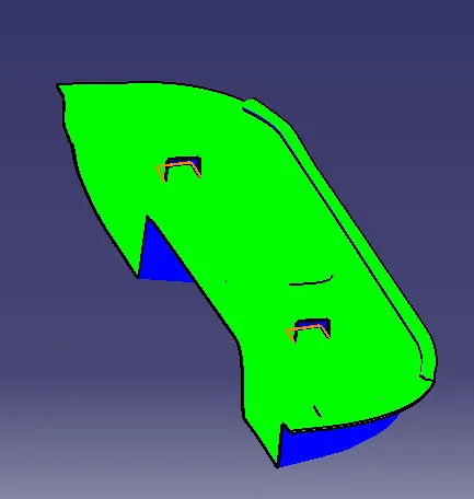
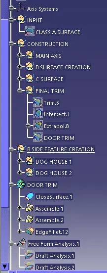
TREE STRUCTURE
Screenshots of the completed design in various orientations