Week 9 - Attachment Feature Creation - Challenge 1
Object:
create the tooling axis and design a rib on coin holder and perform draft analysis on it, by using Catia.
Tooling axis creation:
Tooling axis: the direction of mold open and close and perform the draft analysis on it.
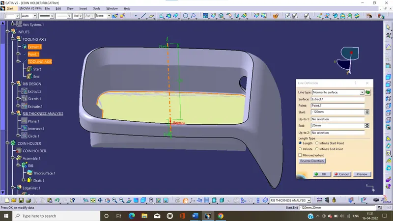
- Firstly, we can extract the base surface and crate the point, by on surface in point command.
- And to draw the line, by normal to surface in line command
- That’s the line is tooling axis.
Design rib:
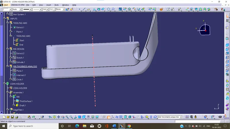
PROCEDURE:
- Extract the bottom surface of the coin holder.
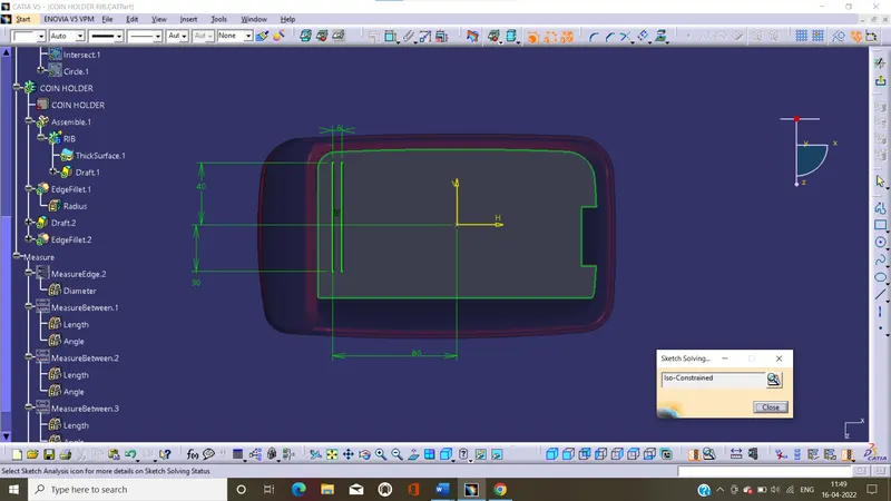
- Draw a positioned sketch on extract surface, and the sketch is in iso-constrained.
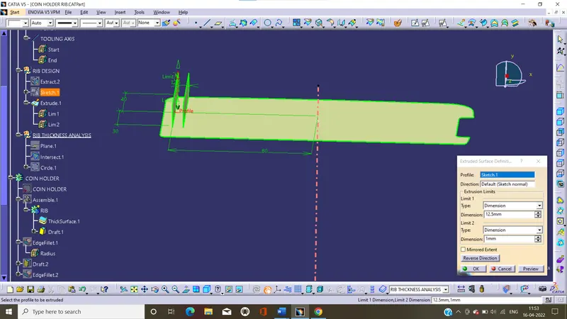
- Extrude the line by use extrude command, and the height of the rib is 5 times the thickness.
- Change it to part design and thicken the extruded surface, the thickness is 0.4 time with wall thickness.
- And perform draft analysis on it, the minimum draft angle is 0.5deg
- Assemble the rib to main part and give the fillet to it, the maximum fillet value is 0.25mm.
- Create the similar way to second rib
Sketch:
Extrude:
Thicken:
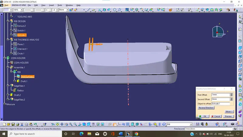
Draft:

Edge fillet:
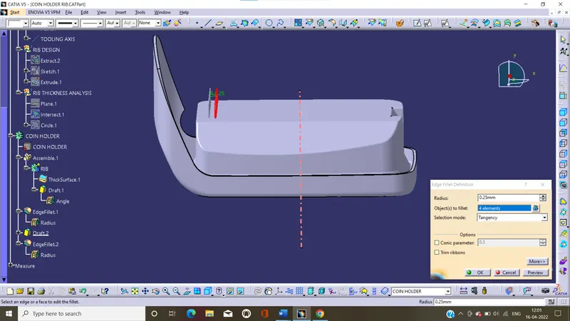
Rib creation report:
Draft: is allows the rib to freely release the mold, the minimum draft is 0.5deg
Rib thickness(W): rib should be designed 40-50% of the nominal wall thickness.
Minimum thickness: minimum rib thickness at the top is 0.75mm
Fillet: the fillet is 0.25mm.
Rib height: rib height is 5 times less than the nominal wall thickness.
Rib spacing: the spacing between ribs is 3:1 steel and we preferred 2:1 but in this 3:1 is preferred.
y/x <3
Width: is 0.4 times of the wall thickness
Rib thickness analysis:
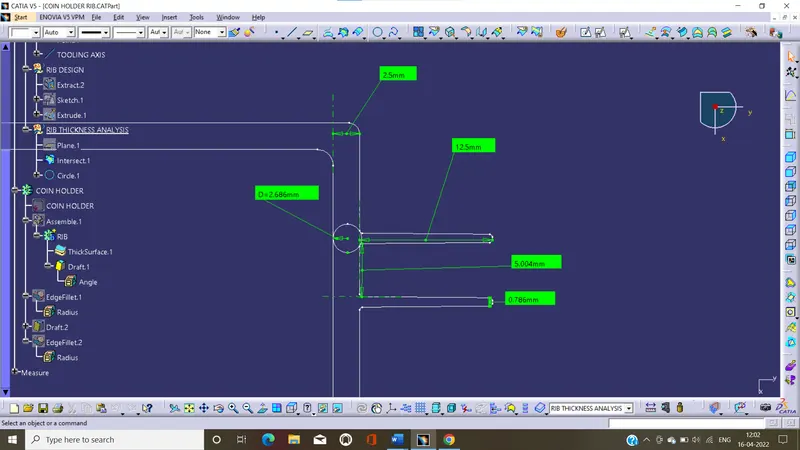
Is performed by all the measuring geometric parameters and ensure it meats the provided design guidelines.
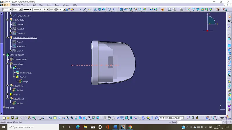
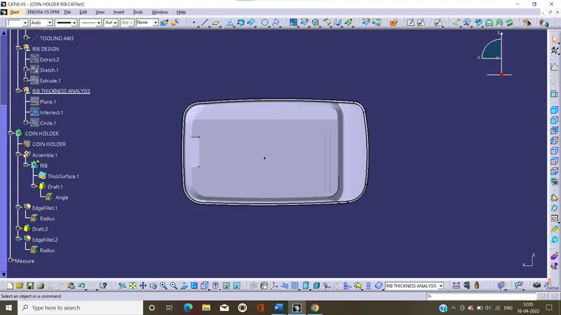
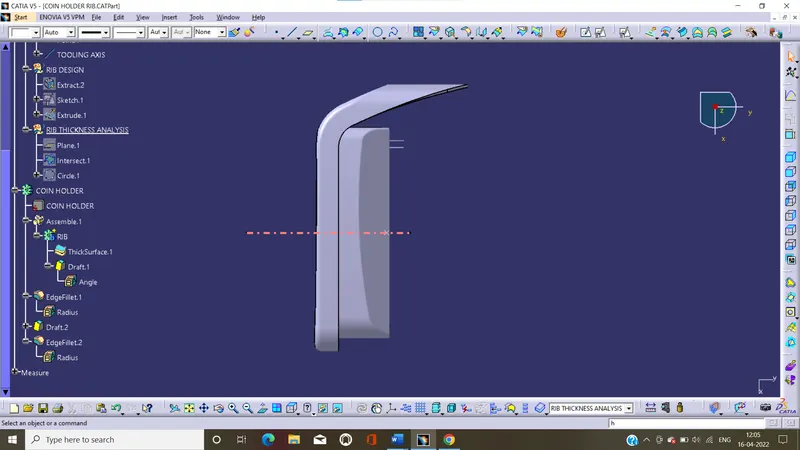
Different orientations of rib design:
Isometric:
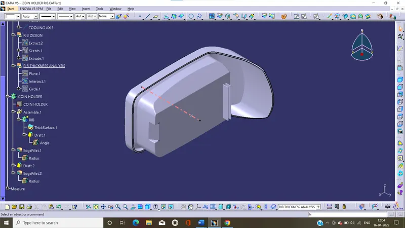
Front:
Side:
Top:
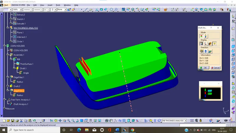
Draft analysis on rib design:
Draft analysis creation:
Draft angle: draft angle is required on all parts because to release the component properly with required direction. Most of the components are required draft angle is 0 to 2 deg, however 3 deg widely accepted
In this we perform the drat analysis on ribs
Isometric:
Front:
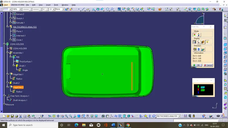
Side:
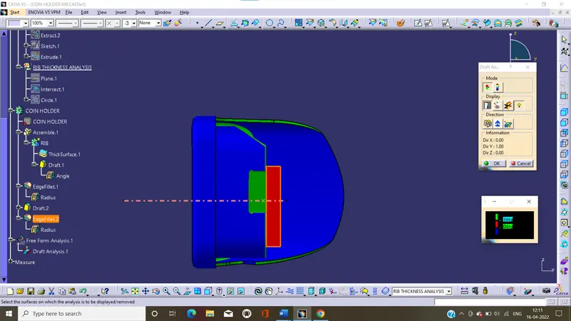
Top:
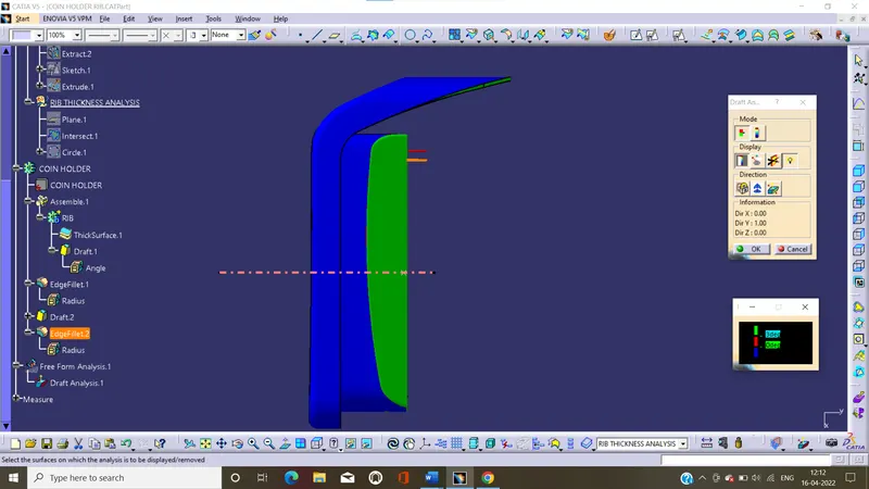
image of colour scale verient:
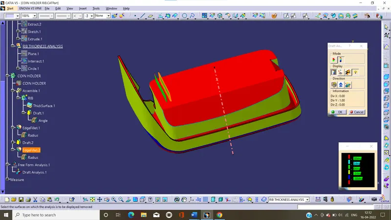
Report:
- In this green color shows the draft angle gathers than the 2 deg.
- The blue color represents the daft angle is between the 0 to 2 deg.
- Red color represents the draft angle is lower than the 0 deg.