Week 9 - Attachment Feature Creation - Challenge 1
Hi colleagues,
The first thing I have seen when I opened the STEP file,in the Tree Structure there is no Tooling Axis and Surfaces of the part and the Part has a name Part.6 – that means I should rename it and I have decided to insert Geometrical Sets CONSTRUCTION and under it TOOLING AXIS also.
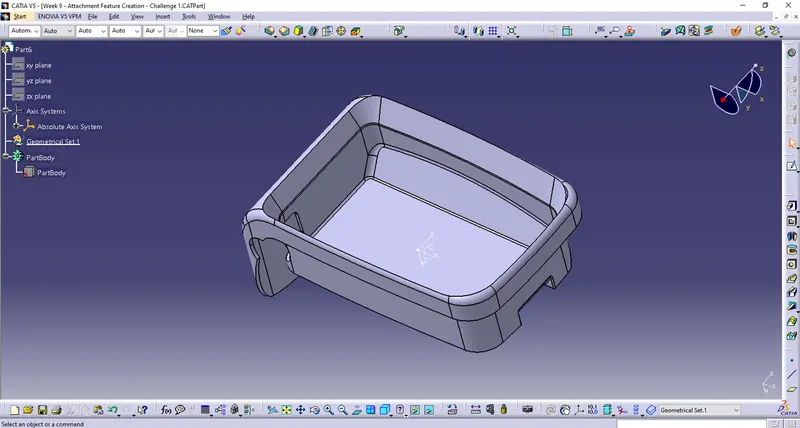
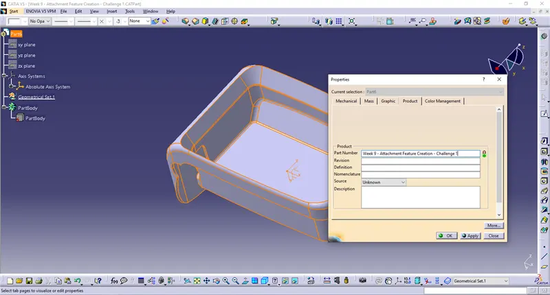
As it is said,I get following.
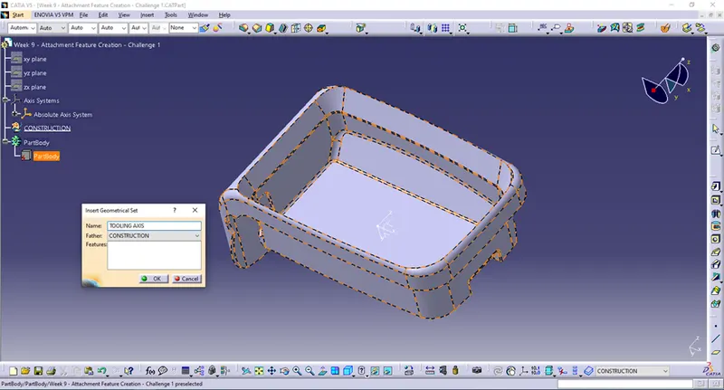
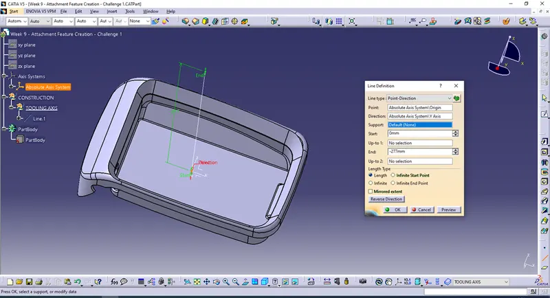
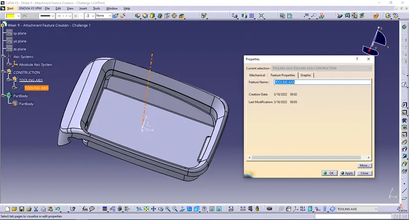
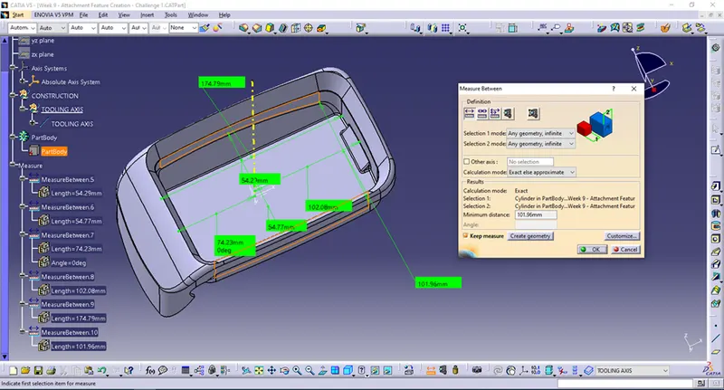
Then under Geometrical Set TOOLING AXIS I have constructed TOOLING AXIS.I have seen Axis System – Absolute Axis System is approximately in the middle of the bottom surface,where I will have my Tooling Axis (on bottom surface).For the purpose of this challenge I will take a position of the Absolute Axis System as a satisfactory solution for a Tooling Axis position.Problem is only,side walls of the part are made without draft (0deg between surfaces when is measured).
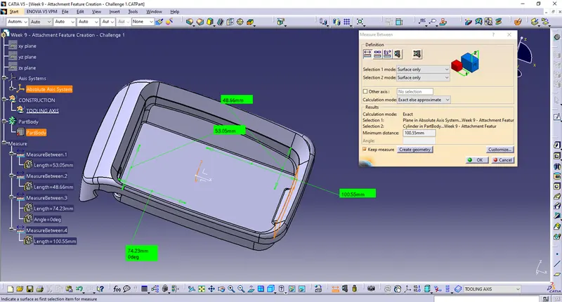
Now I will make a TOOLING AXIS as follows.
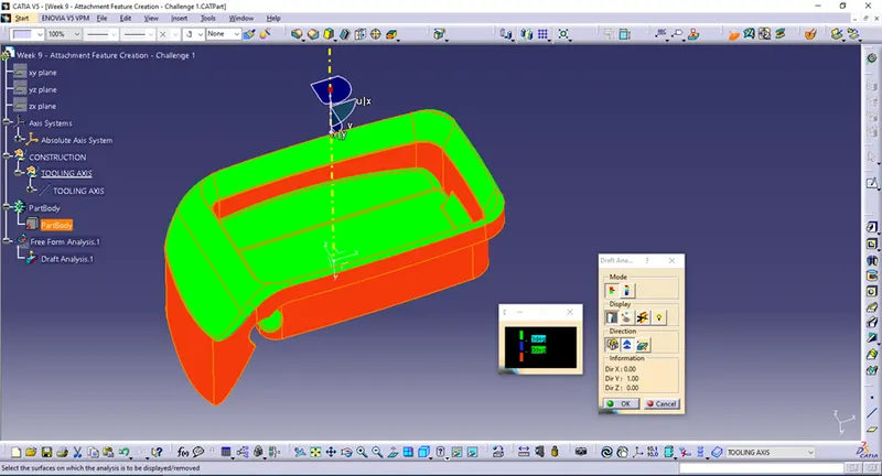
As I already said,0deg on side walls...that will cause a problem and stick on the mould.
Draft Analysis of the given Part shows.
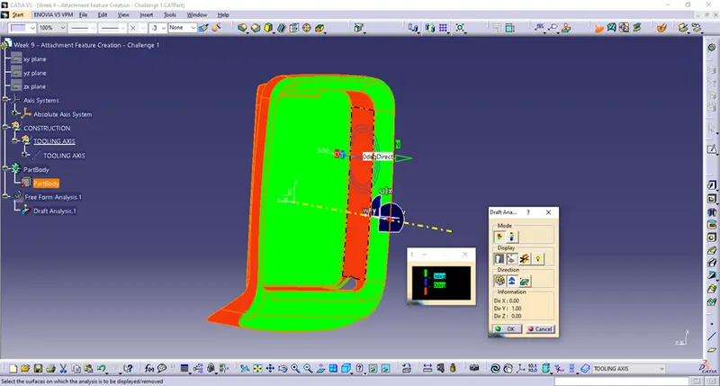
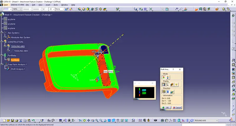
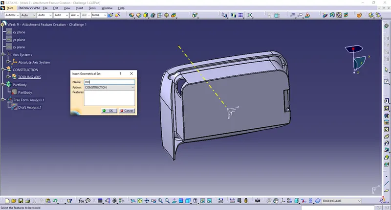
So,now I am going to design Rib feature following all rules required to avoid sink marks and heat resing in critical places.Rib comes on the outer surface of bottom part,therefore I will insert new Geometrical Set under CONSTRUCTION called RIB and I am going to extract bottom surface as follows.
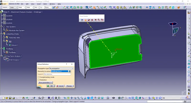
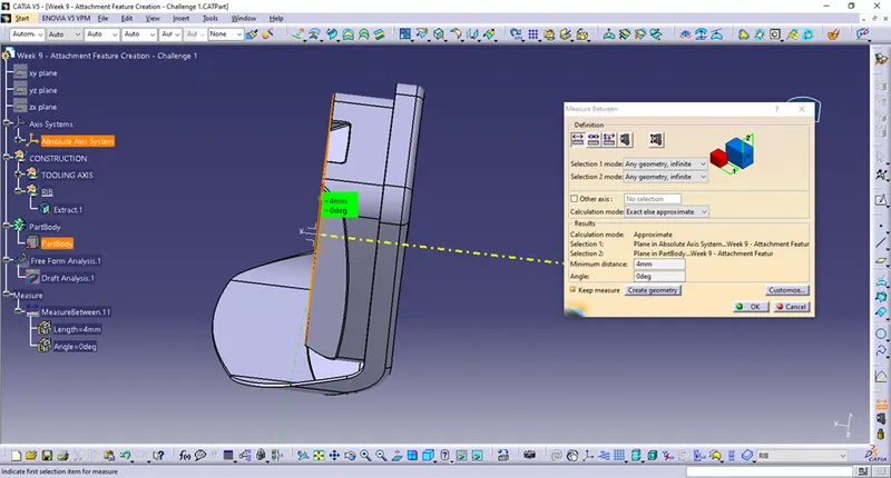
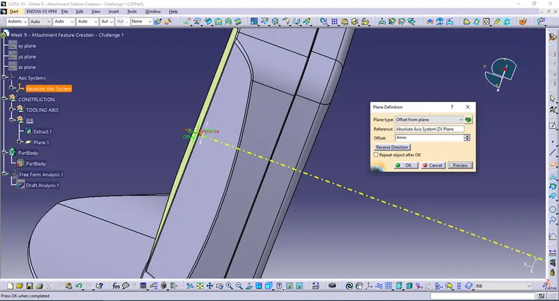
As I have seen there is distance of 4mm between plane of the Axis System and Extract,I will offset one plane for a 4mm regarding plane of the Axis System to get a plane where I can make a Positioned Sketch.
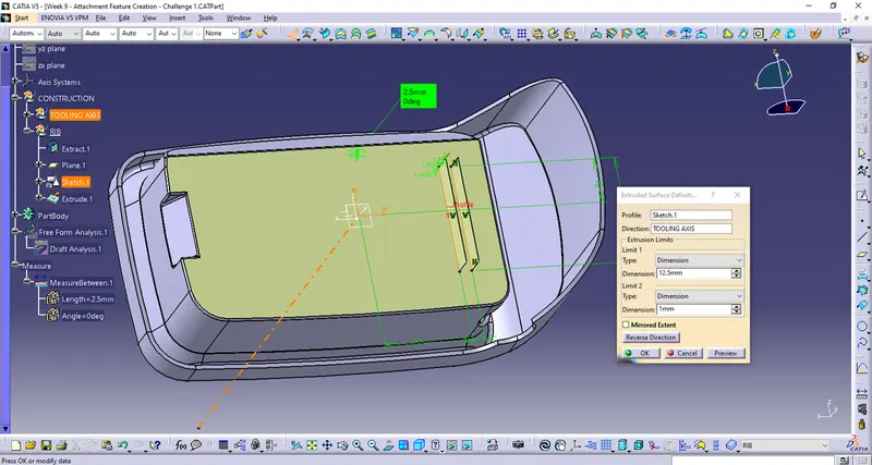
Now on that plane I am going to draw a Positioned Sketch as shown bellow.Positioned Sketch is given with two line for Ribs – and it is taken in consideration one rule for Ribs – spacing between them should be calculated as height/thickness = 2 - 3 prefered ratio is 2 and ratio should not exceed 2 . Thickness of the part is 2,5mm and that is why I have in drawing taken a value of 7mm ,to get a value of ratio 2 – 3.As a remark,for a 2,5mm thick part I will take a height of 12.5mm (maximum height of Rib and the one that is recomended is thickness x 5).
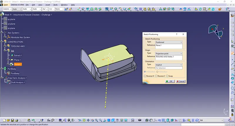
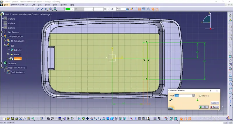
The sketch is positioned.
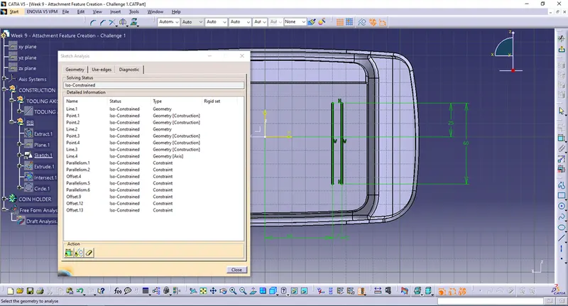
Now I have extruded the lines regarding Rib rule design – Rib height = 5 x Part thickness.Ribs Extrusion direction is direction of TOOLING AXIS.
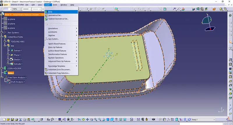
Now I am going to Workbench Part Design and inserting New Body Part,where I will thicken these extrudes.
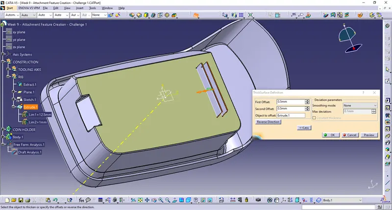
I should take in consideration following rule – Rib thickness = 0.4 x Part thickness.Because Part thickness has a 2.5mm value Rib will have 1mm thickness.
Then I have made a drafts for a Ribs.Minimum draft angle is 0.5deg and Pulling direction TOOLING AXIS.
I am getting as follows.
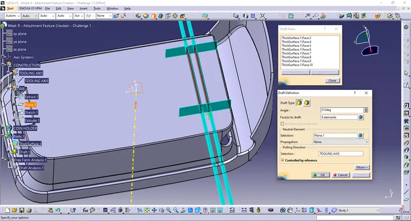
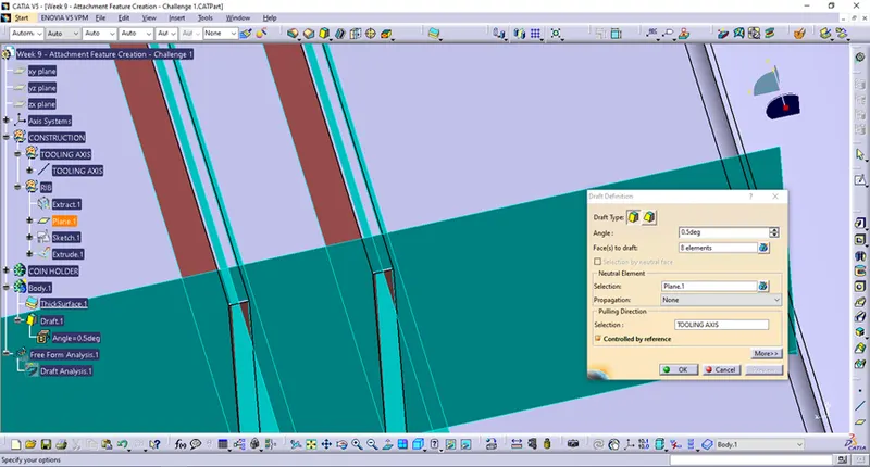
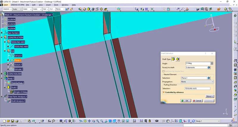
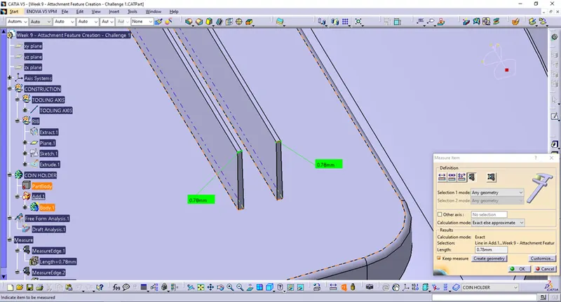
Now I am joining those Body Parts in one Body Part – COIN HOLDER and checking Rib thickness on top.The rule is,it should be 0.75mm or higher.Value is 0.78mm – it satisfies.
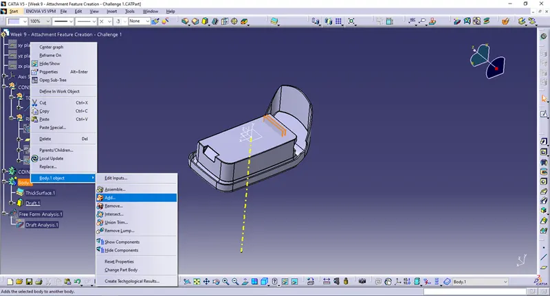
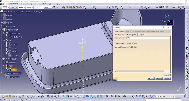
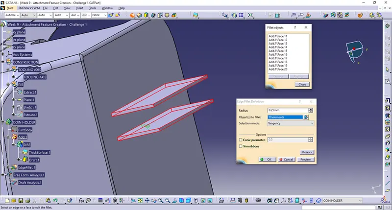
Then I have changed the name of Body.1 to RIBS and fileted the RIBS.Fillet/Radius value for Ribs is 0.25mm maximum.
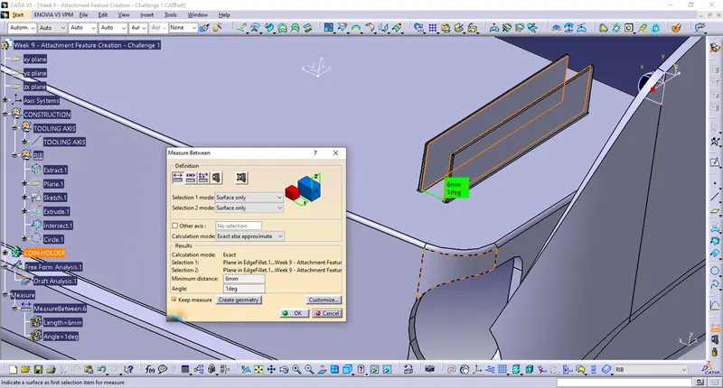
I have checked spacing between Ribs.it should satisfies rule: Rib height / Rib spacing = (2 till 3).By me is 12.5 / 6 = 2,08 it satisfies.Draft is 1deg,that means 2x0.5deg - it is good also.
And at least I have to check thickness of the Rib root – the rule it is not allowed to exceed ±30% of part thickness.That is why I should make intersect of the part to see the root value of Rib.
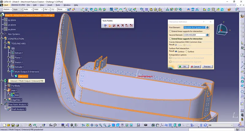
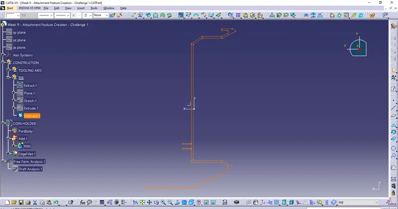
Now check goes as follows – it should be drawn tritangent circle using extracting curves option.
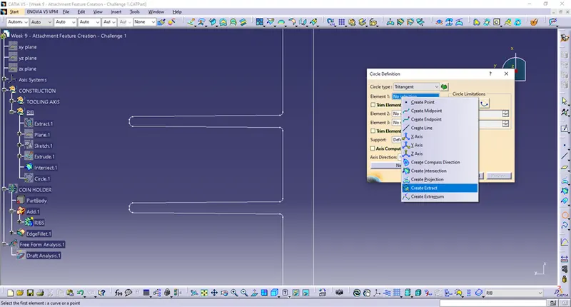
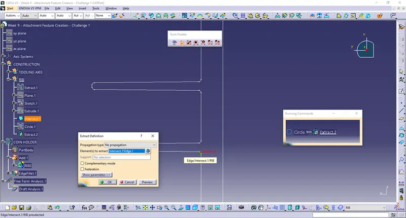
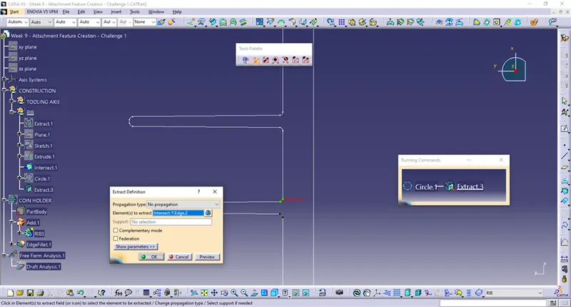
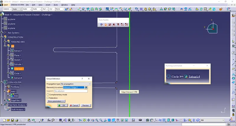
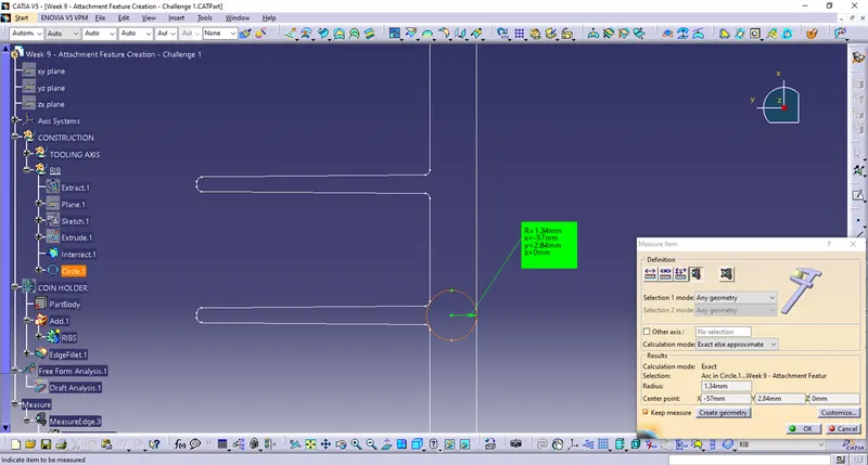
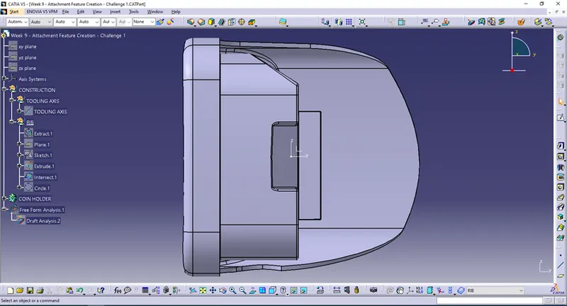
So,it can be seen diameter of the root Rib is 2.68mm and Part thickness 2.5mm it not exceed ±30% of part thickness (ratio is 1.072).
On the end I have done draft analysis on final part with ribs,it fullfils requirements for rib construction.
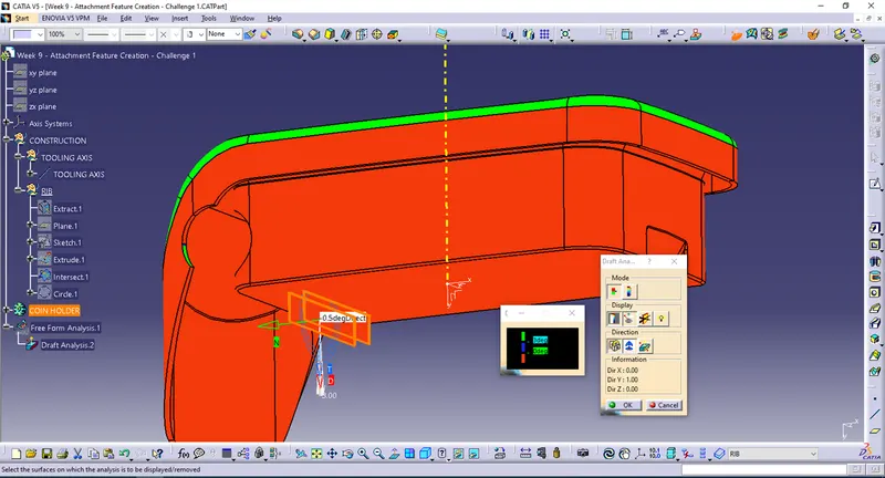
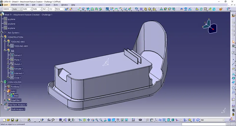
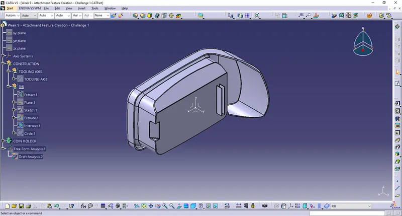
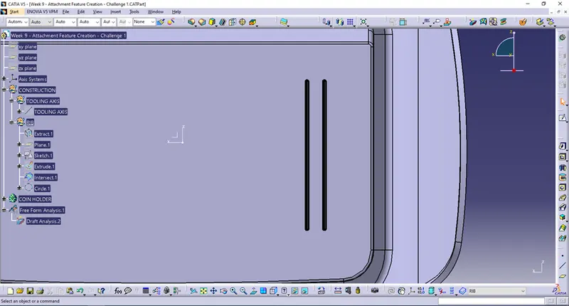
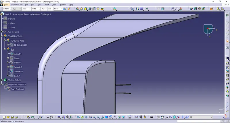
RIB is designed following all rules and parameters for design (rib thickness,draft,spacing between ribs, height,value top of rib,radiuses,root rib value) and so designed rib satisfies given requirements.
Various views of the part,where Rib design is visible is given bellow.
That is all fellows.
Best regards,
Ivan Tole