Week 9 - Attachment Feature Creation - Challenge 1
Objective: Creating a Rib as per Design guidelines for the coin holder and draft analysis
Draft Analysis: The draft analysis command will enable as to detect if the part that is drafted is easily removed while the manufacturing process. This type of analysis is performed based on the color ranges identifying a zone on the analyzed element where the deviation from the draft direction the minimum draft angle for the plastic components will be 3 degrees.
Rib Design:Rib provide a means to economical stiffness and strength in molded parts without increasing overall wall thickness.
Rib is a thin, wall-like feature typically designed into the geometry of a part to add internal support to walls or other features like bosses. Rib increases the bending stiffness of a part. without ribs, the thickness has to be increased to increase the bending stiffness. Adding ribs increase the moment of inertia, which increases the bending stiffness. The rib thickness should be less than the wall thickness to keep sinking to a minimum. The thickness range from 40 to 60 % of the material thickness. In the addition, the rib should be attached to the base with a generous radius at the corners.
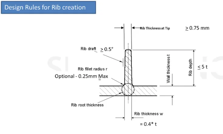
- The nominal wall thickness of a plastic component: 3mm
- A deviation of +-30% from the wall thickness is accepted
- Example for 3mm thickness
- 2.1 mm is minimum
- 3.9 mm maximum accepted
The ideal draft for a component is 3deg
Minimum 0.5 deg accepted for ribs.
Rib design plays a most valuable supporting role in many plastic applications. They generally serve two primary purposes in a plastic part to add strength and function. They can also prevent aesthetic defects and non-fill risk.
Designers commonly try to increase the strength of a part by making its walls thicker. Unfortunately, walls that are too thick are subject to warpage, sinking, and other defects. The advantage of using ribs is that they increase the strength of a part without increasing the thickness of its walls. Because less material is required, ribs can be a much more cost-effective solution as well
Design Rules for the ribs in Class A surface
- Draft = 0.5 deg per side minimum
- Thickness = typically 40% wall thickness
- Height = 5*wall thickness
- Spacing = 3:1 steel height/width raio max
- Minimum thickness at tip = 0.75mm
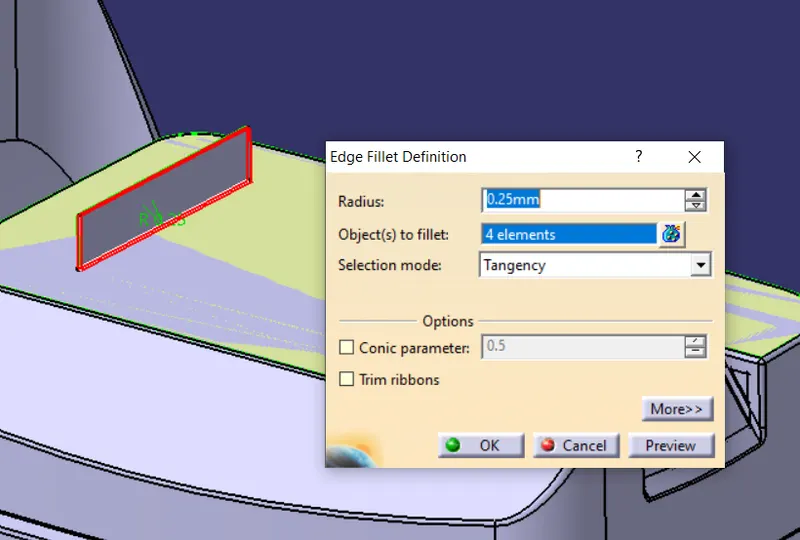
- Radius of fillet = 0.25mm maximum
- Ribs on opposite side of wall should be offset.
- Ribs should be connected to other structural feature where possible.
Rib design involves five main issues
1. Thickness
2.Height
3.Location
4.Quantity
5.Manufacturability
Tooling axis:
Then we need to create a Tooling axis for draft analysis and manufacturing purposes, to create a tooling axis mainly for tooling axis is considered as in Holes as a primary area to create tooling axis.
Extract a surface then insert a point at the center of the surface plane, place an axis system on the point by selecting sketch mode creating a point to direction option that creates a final tooling axis.
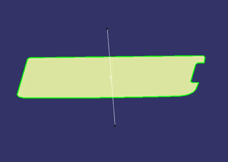
Procedure for creating Rib design
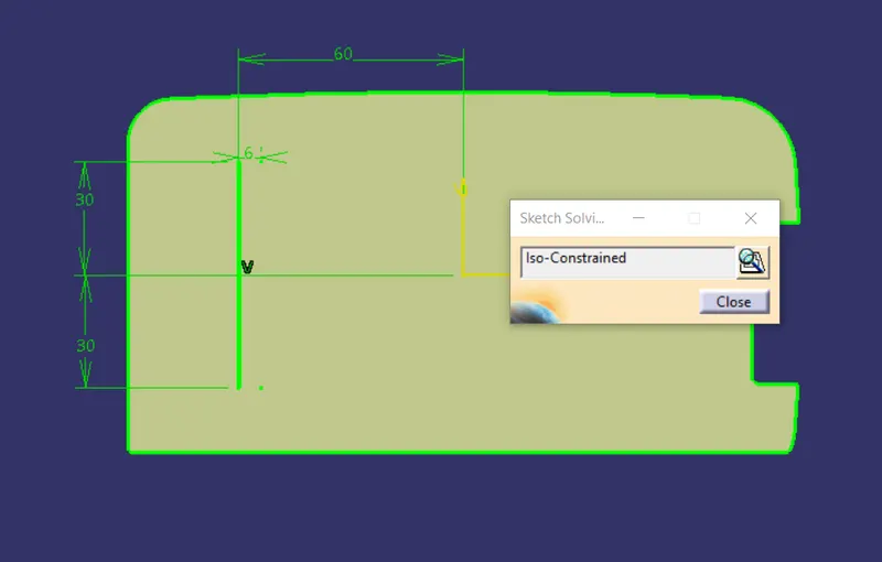
Step 1 :Create a sketch on the extracted surface all sketch should be in iso constraint.
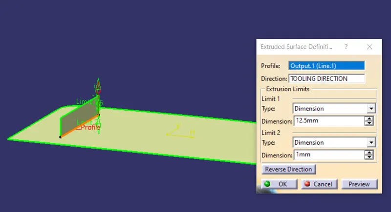
Step 2: Extrude the sketch along a tooling direction, Height of the rib should 5* thickness of the components.
Height of rib= 5*thickness of the components
H=5*2.5
H= 12.5mm for upward direction and for downward 1mm it will be join with the components also.
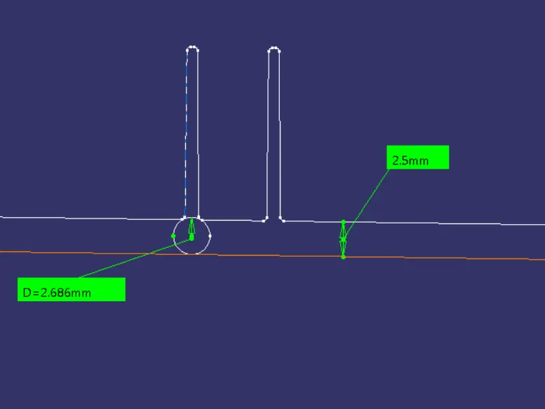
Step 3 : Provide a thickness for up to 1mm as per the Rib design guidelines thickness is typically 40% of wall thickness as in the coin holder thickness is 2.5mm
T= 0.4* nominal wall thickness
T= 0.4*2.5
T=1mm as thickness for the rib wall
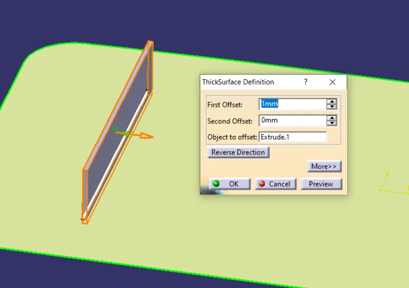
Step 4:Give a draft angle for the rib for all the four face,along a tooling direction the minimum draft angle for the rib is 0.5deg per side minimum.
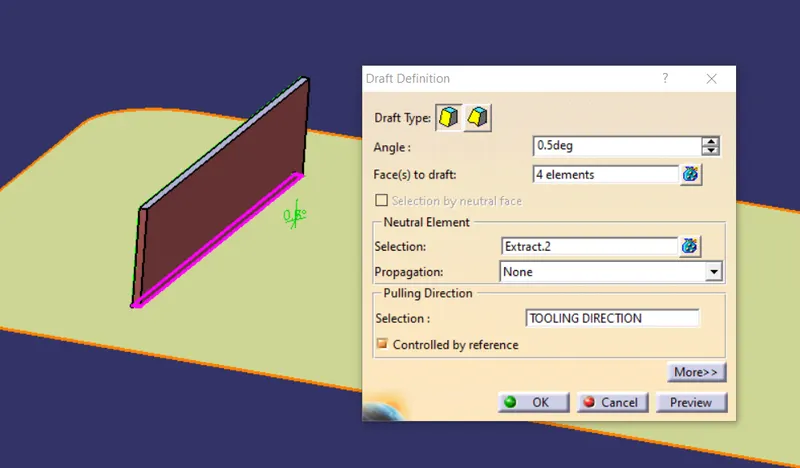
Foe the given the draft minimum thickness at the tip is greater than 0.75mm
Step 5: Assembly the rib with main part body componnts.
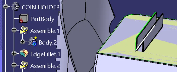
Step 6:Edge fillet of rib
Edge fillet for the rib is 0.25mm is allowed for all face.
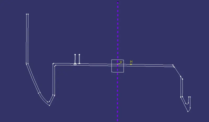
Step 7: Intersect XY Plane with a components of part body
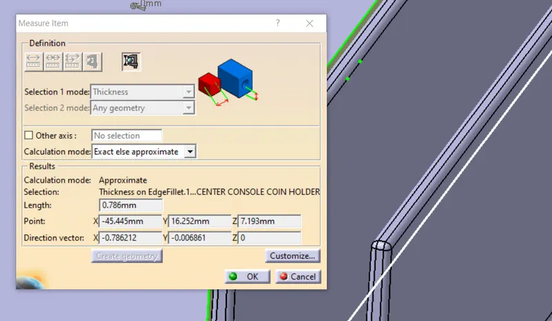
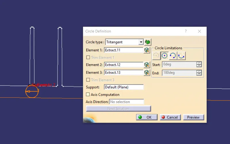
Step 8: Checking a rib root thickness, Using a tritangents circle from the circle defination.
Checking measurement of the rib root thickness
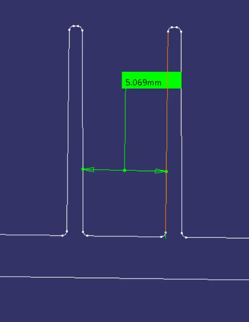
Creating a spacing for rib to get more than one
Spacing =3:1 steel height
Height(mm)/Gap(mm) =3:1
Note: Gap should > 3mm
Y/X =3
12.5/X=3
X=12.5/3
X= 4.167 almost equal to 5mm
Step 10: Repeat same procedure to get Rib
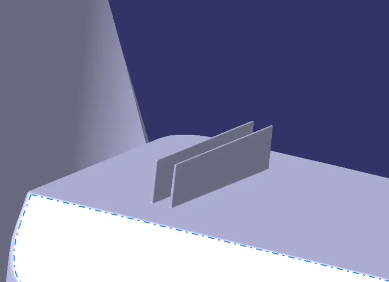
Final Result
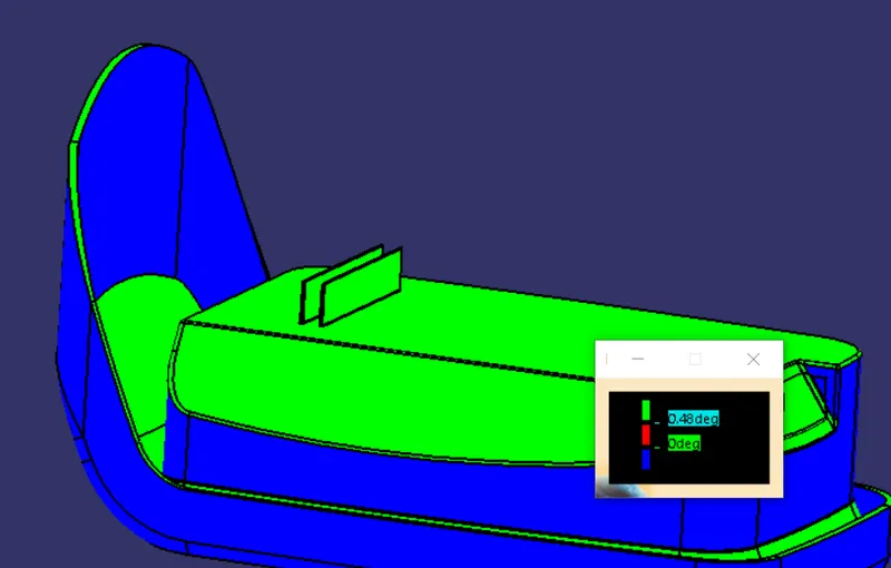
Draft analysis for Rib
The draft analysis command enables to detect if the part drafted will be easily removed. This type of analysis is performed based on the colour ranges identifying zones on the analysed components where the deviation from the draft direction at any point.
It's also important to remember that draft angles are just for the components of an effectively designed in the injection-molded piece. Design manufacturing is one of the easiest ways to improve the quality and efficiency of the injection molding process, and it never damages to stay up to speed on all injection molding.
Procedure
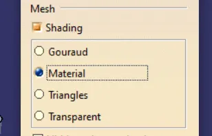
Step 1: change a mode to material
Step 2: Go to toolbar>Insert>Analysis>Feature draft analysis
- Drag the compass from the draft analysis box on the tooling axis and place it properly
- Click on the lock so the compass will get locked to the tooling axis.
- click ok
- Analysis the color of the failing and passing surface.
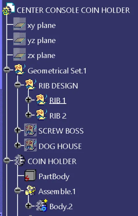
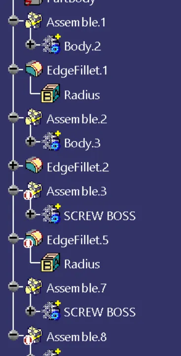
Feature tree
Conclusion: The creation of a rib on the coin holder has been successfully done as per Rib design guidelines.