Week 9 - Attachment Feature Creation - Challenge 1
DESIGN OF RIBS ON COIN HOLDER COMPONENT:
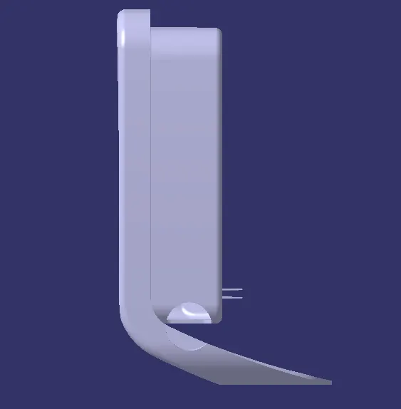
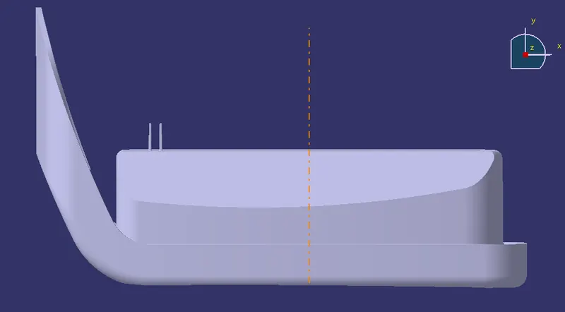
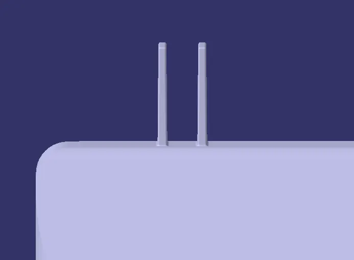
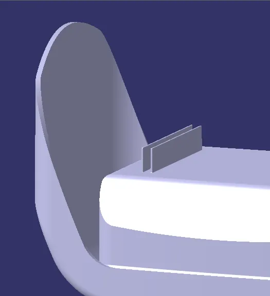
The objective of this assignment is to create the Ribs on coin holder that was designed on previous assignment by following the design rules for rib creation.
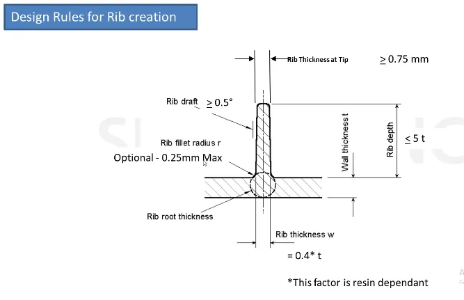
DESIGN RULES FOR RIB CREATION:
DRAFT ANALYSIS:
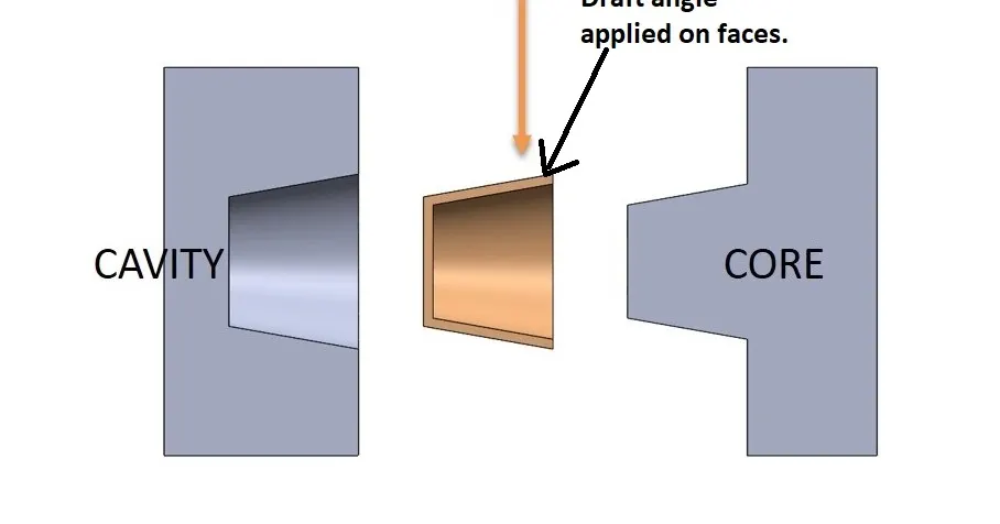
- Draft Analysis is carried out in order to check that all faces have a proper draft angle (minimum 3 degree) in order to manufacture the component easily.
- Draft Angle is given on both the outer and inner faces so that during ejection of the component from the mold the part will easily be ejected without having much rubbing friction.
- If draft angle is not provided to the parts, then during ejection of the part the entire part would get rubbed against the core and cavity and there will be much rubbing friction induced which will make the ejection process more difficult and as a result the part, core and cavity will get damaged.
- In order to avoid this issue Draft Angle is given on all faces.
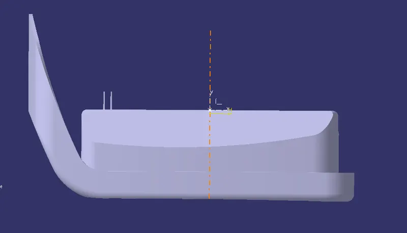
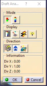
- To perform the draft analysis, we need the Tooling Axis.
CREATION OF TOOLING AXIS:
- To create the Tooling Axis first we need to decide the core and the cavity side.
- After deciding which side will be on the cavity part and which one on the core part then we can easily get our tooling direction.
- Now we have to identify the faces on which draft angle should be given so that it clears the Draft Analysis test.
- In this component as we have a flat base so the Tooling axis must be normal to the base.
- First a point is created at the center of the face then a line is drawn normal to the surface which becomes our Tooling Axis.
- Now we can perform our draft analysis and check if all the faces have a draft angle or not.
DRAFT ANALYSIS ON THE CLASS A SURFACE:
COLOR CODE:
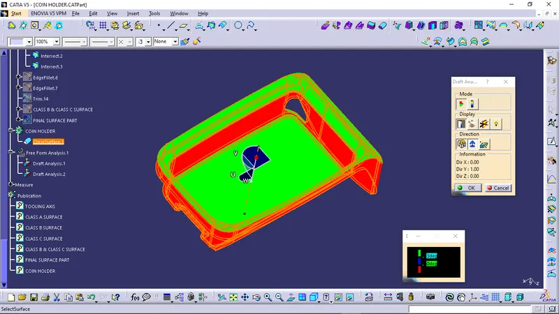
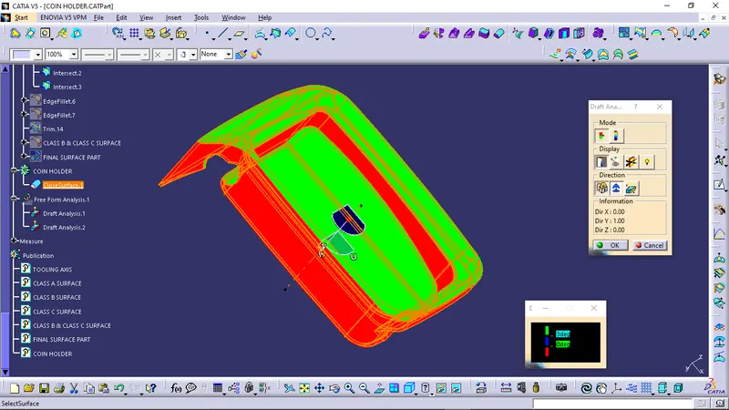
- GREEN COLOR: For draft angle more than 3 degree.
- BLUE COLOR: For draft angle between 0 to 3 degrees.
- RED COLOR: For Negative draft angle.
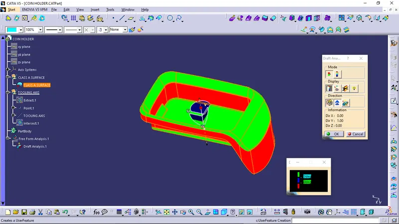
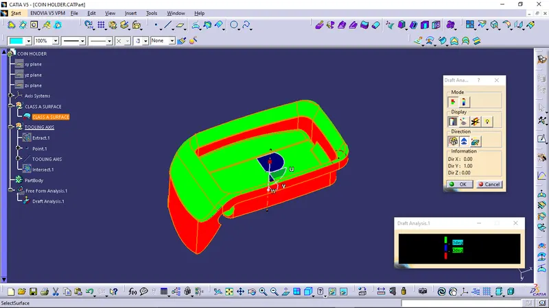
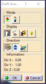

- From the above draft analysis, we can clearly observe that there are many faces on the Class A Surface which does not abide the Draft Angle rule for the component to get manufactured.
DRAFT ANALYSIS OF THE FINAL PART:
DESIGN OF RIBS:
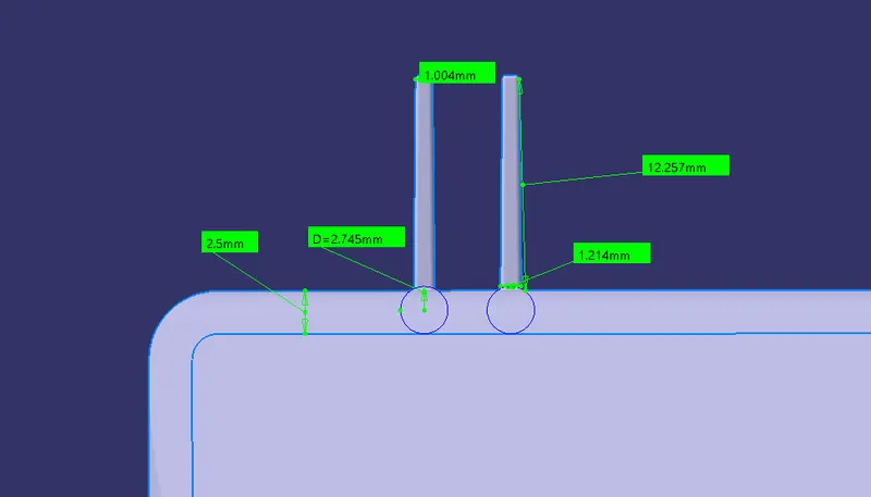
1. RIB HEIGHT: 5*T
Where T = Nominal wall thickness
Rib Height = 5*2.5 = 12.5mm
2. RIB THICKNESS: 0.4*T = 1mm
3. RIB THICKNESS AT THE TOP: > 0.75mm
4. FILLET RADIUS: 0.25mm Maximum
5. DRAFT: 0.5 deg per side and on all faces
6. RIB ROOT THICKNESS: To be carried out
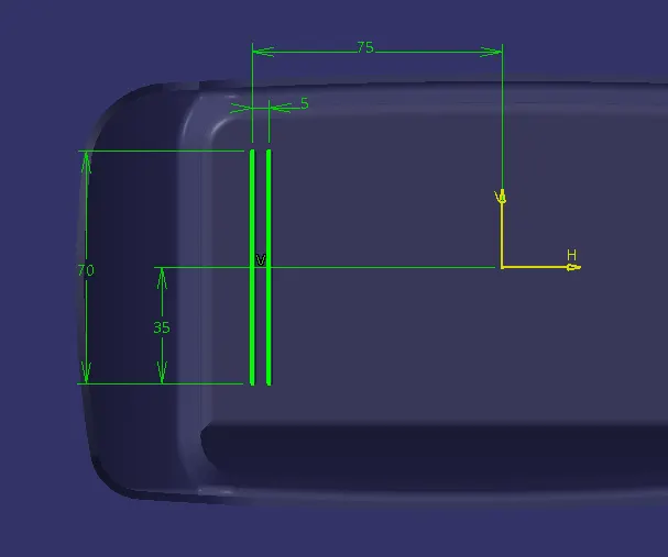
7. SPACE BETWEEN RIBS:
`(Height)/(Width)=3/1 or 2/1`
FOR RATIO 3:1
Width = 4.17mm
FOR RATIO 2:1
Width = 6.25mm
RIB ROOT ALAYSIS:
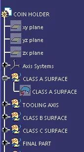
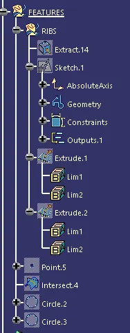
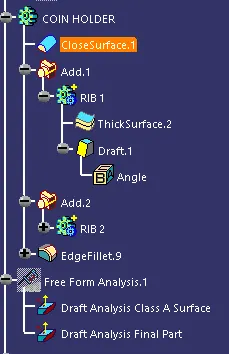
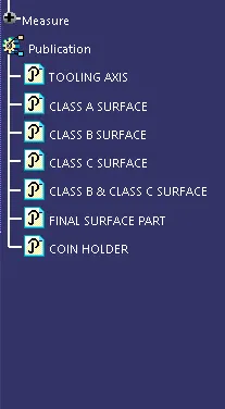
TREE STRUCTURE:
DIFFERENT VIEWS OF THE PART:
ISOMETRIC VIEW:
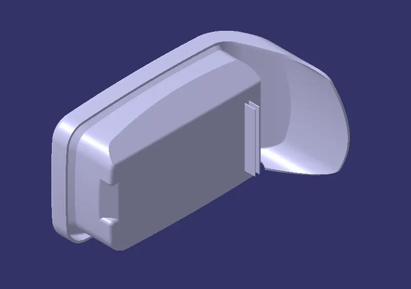
FRONT VIEW:
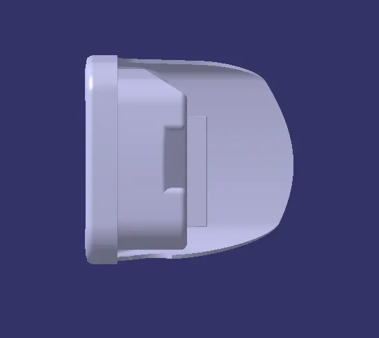
BACK VIEW:
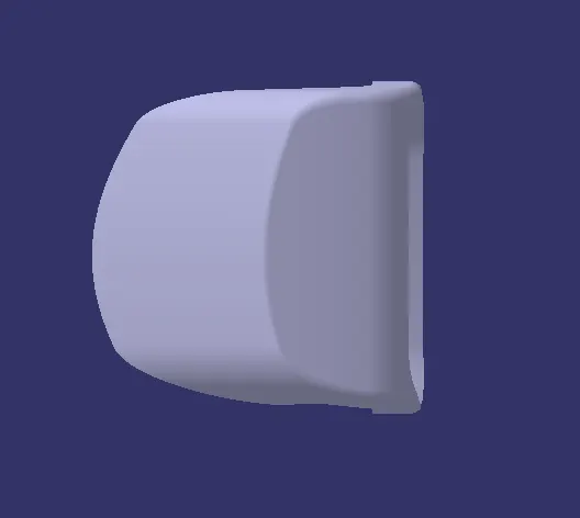
LEFT VIEW:
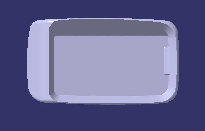
RIGHT VIEW:
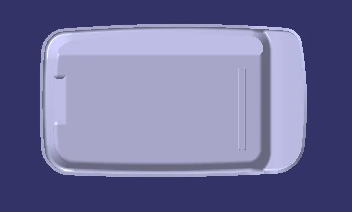
TOP VIEW:
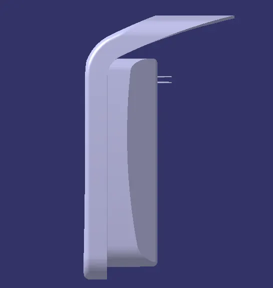
BOTTOM VIEW: