Week 9 - Attachment Feature Creation - Challenge 1
ATTACHMENT FEATURE CREATION - CHALLENGE 1
OBJECTIVE:
To design ribs for a center console coin holder following certain guidelines.
RIBS:
Ribs are a feature in plastic injection molded parts.They are thin extensions that run perpendicular from a wall or plane.They are commonly used to provide additional support and strength to a part without increasing the overall wall thickness.
PURPOSE:
They are commonly used to provide additional support and strength to a part without increasing the overall wall thicknesswhich will complicate the injection moulding process.
ADVANTAGES OF CREATING A RIB:
- Locating and arresting components of an assembly.
- Providing alignment in mating parts
- Can be used as guides for mechanism
RIB DESIGN GUIDELINES FOR A PLASTIC PRODUCT:
Ideal draft for a rib - a draft of 0.5 mm minimum at each side. Draft more than 0.5 would directly affect the rib thickness at tip and the height of the rib
Rib thickness - 0.4*Thickness of the component. For components having 1mm of wall thickness the rib thckness should be the same as wall thickness. Thinner ribs are very difficult to fill.
Rib thickness at tip - 0.75 mm minimum because the molten material can't reach till the end if it goes below 0.75 mm
Rib fillet radius - 0.25 minimum and for thicker component 0.5 is the maximum
Rib height - 5*Thickness of the component. Ribb thicknes directly affects the mould ability,if we tend to disobey the rule that would cause sink marks on the component.
Rib root thickness - Thickness of the component +/- 30% is acceptable. More than it it would probably cause a sink mark
Spacing b/w ribs - Y/X < 2 . The spacing sould be 2 or lesser than it
where,
Y is the height of the rib
X is the distance between the ribs
TOOLING AXIS:
Tooling axis is normally created along the surface as it is flat.
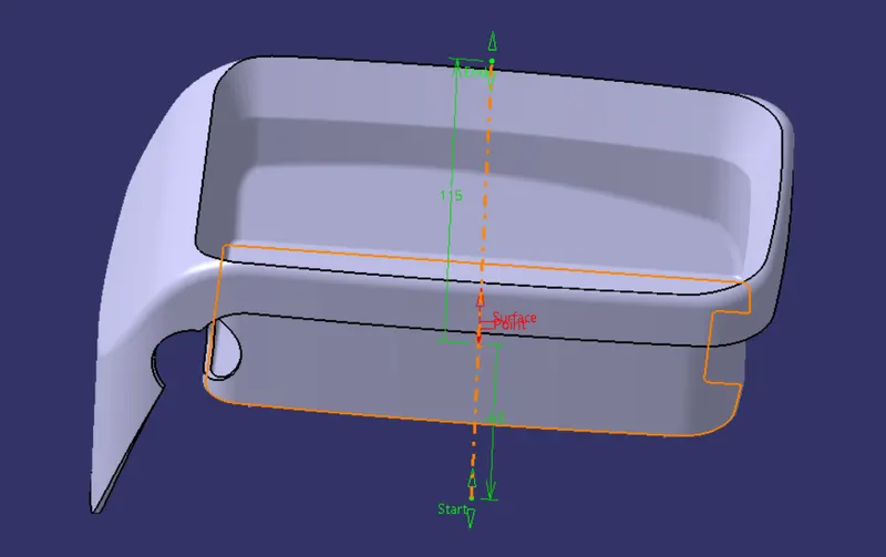
RIB DESIGN:
Sketch solving status:
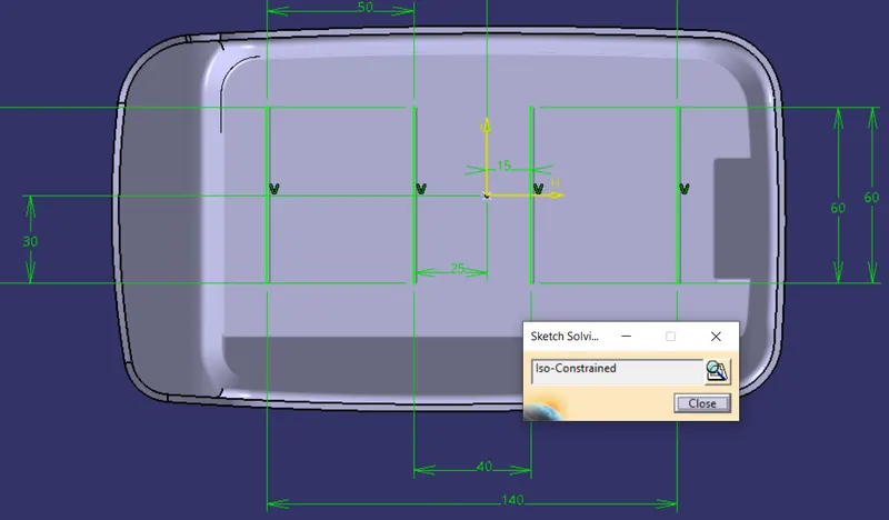
Rib height:
5*Thickness of the component
5*2.5 = 12.5 mm
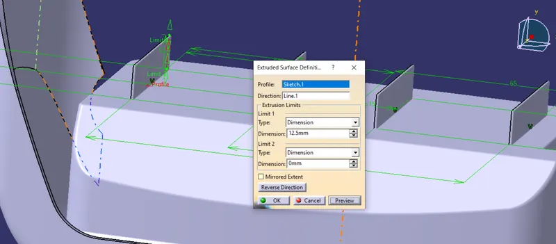
Rib thickness:
0.4*Thickness of the component
0.4*2.5 = 1mm
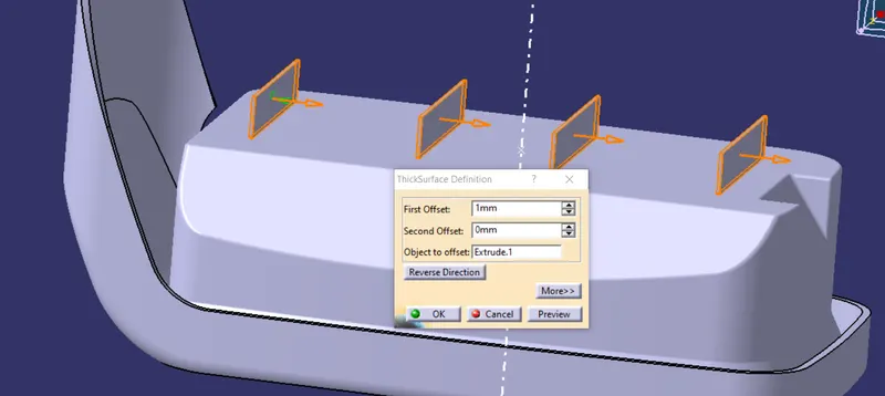
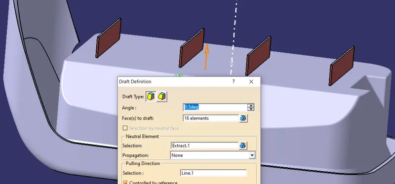
Draft:
0.5mm
Pulling direction : Tooling axis
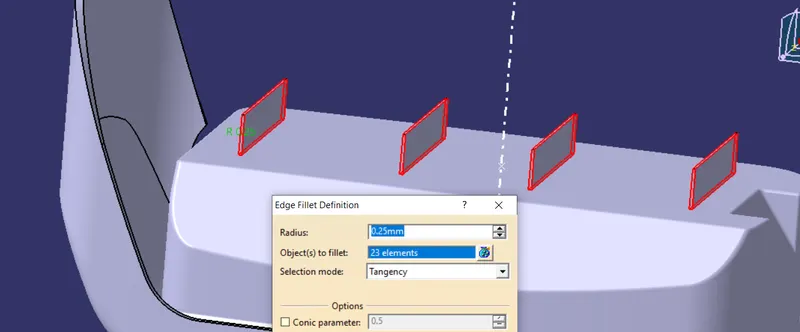
Fillet:
0.25 minimum
Rib root thickness:
Thickness of the component +/- 30 % = 3.25/1.75
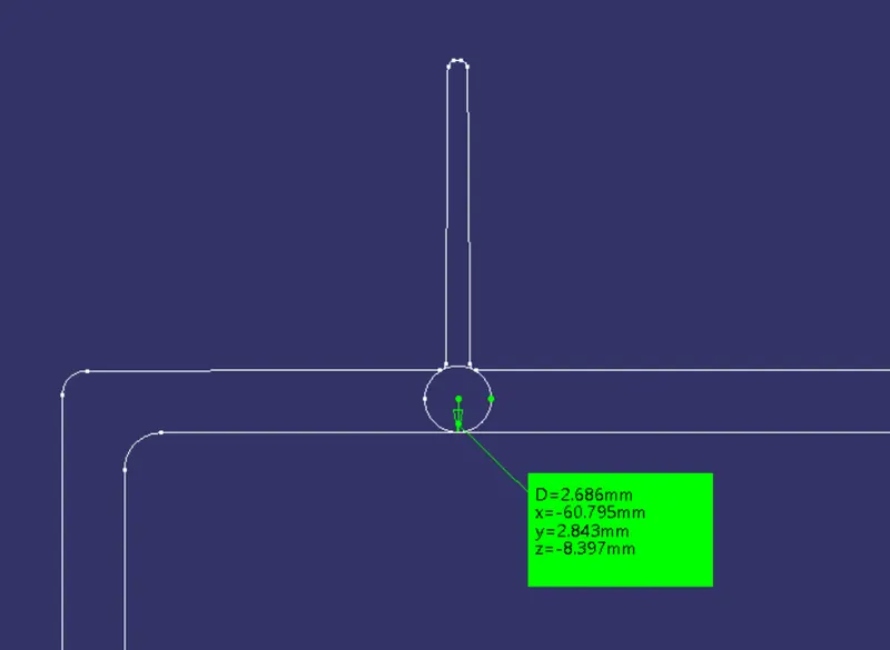
Here it is 2.68 and it is acceptable.
Spacing:
Rib spacing must be 2mm or more than that.
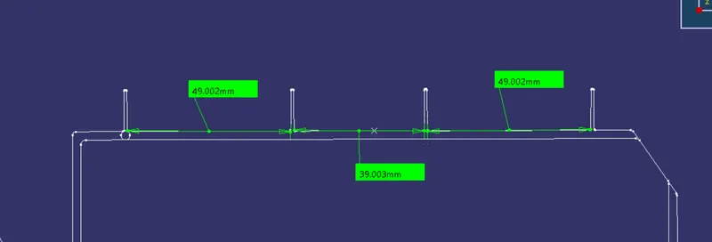
Here 4 ribs are created and all of them spaced more than 2 mm.
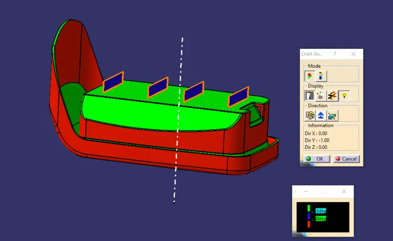
DRAFT ANALYSIS:
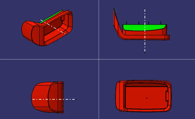
VARIOUS ORIENTATION:
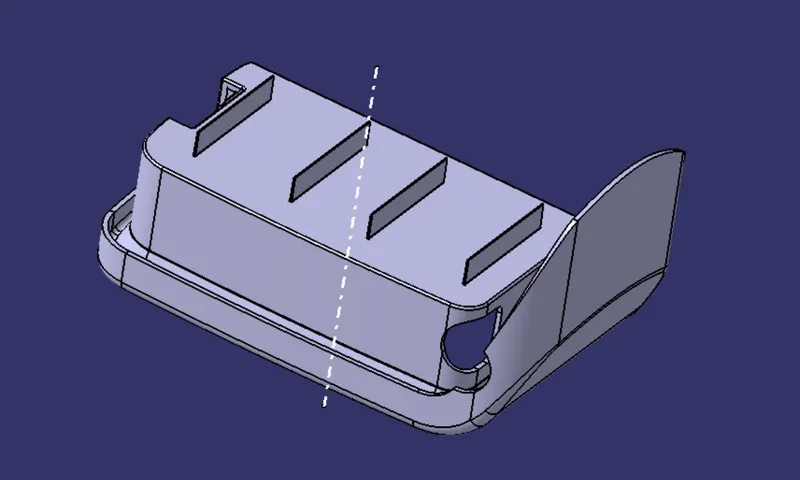
FINAL PRODUCT:
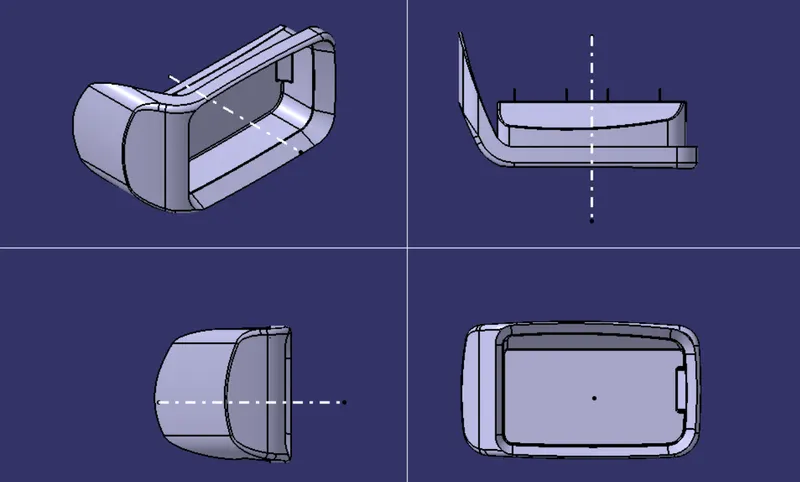
VARIOUS ORIENTATION OF THE PRODUCT:
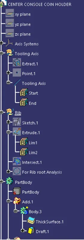
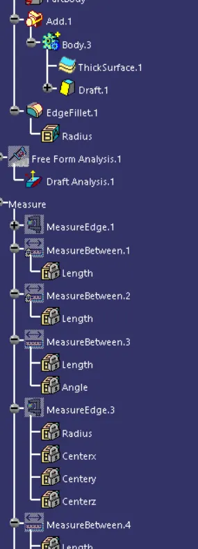
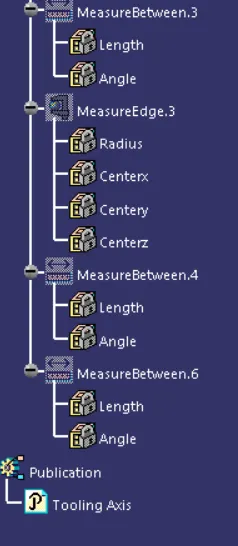
TREE STRUCTURE:
CONCLUSION:
Ribs are designed on the coin holder following all rib design guidelines.
Software used : CATIA