Week 9 - Attachment Feature Creation - Challenge 1
AIM: Create the rib for the Centre console coin holder
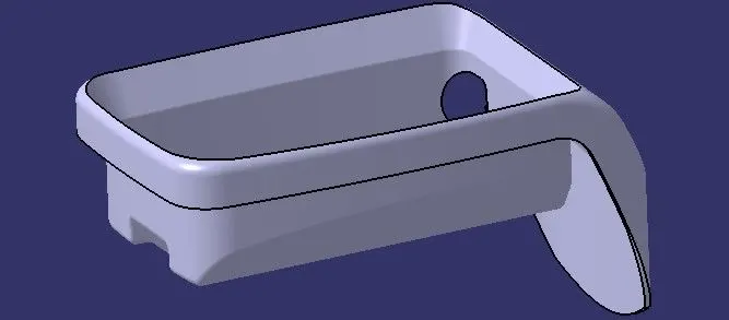
THEORY :
When should Ribs be added?
Ribs play the most valuable supporting role in many plastics applications. They generally serve two primary purposes in a plastic part – to add strength and function. They can also prevent aesthetic defects and non-fill risks.
Adding and adjusting ribs to a part design can generally happen at three stages: during initial part design, after Moldflow simulation of the part, and after molding parts.
Initial Design: At the initial design phase, you want to consider areas of flatness and user stress for rib placement. Following standard rib design guidelines can help you design optimal ribs.
Post Moldflow: After the initial design, Moldflow simulation can help you visualize how molten plastic will flow through and fill the mold to form the plastic part. From here, you can see the risk areas of plastic fill. In thick areas expected to have a non-uniform shrink, coring out can reduce the risk of sinking. Sometimes ribs create locally thick areas that are susceptible to shrink. Removing unnecessary ribs can help eliminate these shrink risks. In thin or high-pressure areas projected to experience non-fill, adding ribs can reduce these risks.
Post Molding: Once you have molded parts in hand, part problems will inform where the addition and subtraction of ribs may benefit part quality. If you see warp, adding ribs can help. If you see a sink under ribs, modifying or removing ribs can help. Adding ribs are steel-safe changes, meaning that an existing mold can easily be modified to incorporate them. Removing ribs grows more complicated and costly because metal needs to be added to the tool. Incorporate fewer ribs into your initial design if you are at all unsure.
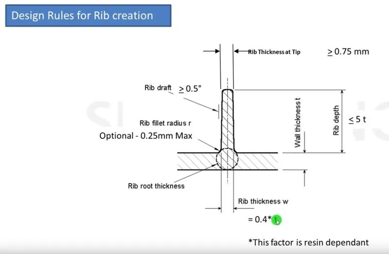
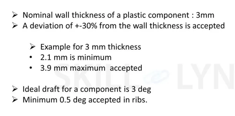
RULES OF CREATING RIBS :
PROCEDURE FOR CREATING RIBS :
STEP 1: Sketch for the length of rib.

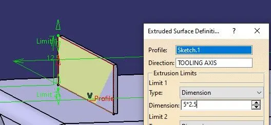
STEP 2: Extrude the sketch.
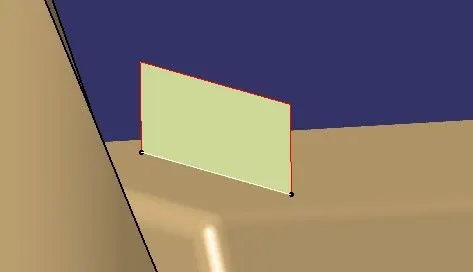
STEP 3: Height of rib.
- The height of the rib should be 5*Thickness of components.
STEP 4: Thickness of rib.
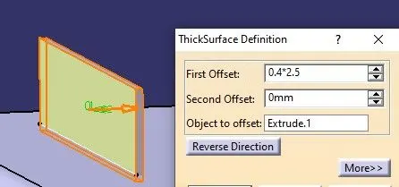
(Thicken the extract by switching the workbench to Part Design workbench inside Part Body)
- The thickness of the rib should be 0.4*Thickness of components.
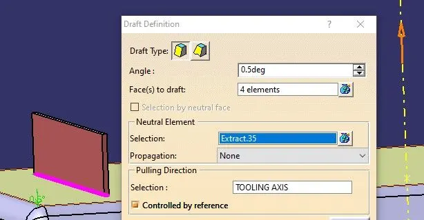
STEP 5: Giving Draft to the ribs from all four sides.
- The draft should be 0.5 degrees from the base.
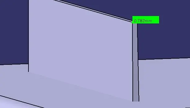
NOTE: After giving draft, the top edge of the rib should be greater than 0.75mm
STEP 6: Assemble the Rib Part Body inside the Main Part Body Component.
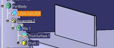
STEP 7: Edge Fillet of rib.
- Edge Fillet of 0.25mm is allowed to all faces of the rib.
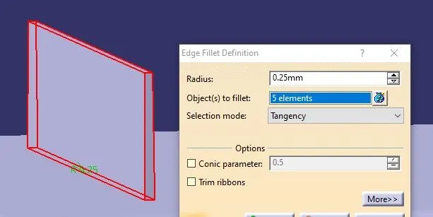
- View after edge fillet.

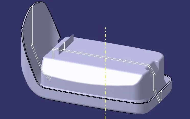
STEP 8: Intersect XY Plane with Component Part Body.
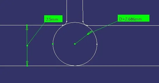
STEP 9: Checking Rib Root Thickness.
- Using Tritangent Circle from circle definition.
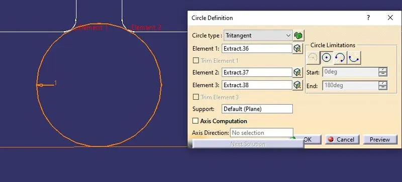
STEP 10: Checking Measurements of Rib Root Thickness.
Thickness with rib should be 30 % of model thickness
STEP 11: Creating more ribs.
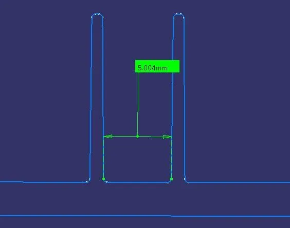
`(Height (mm))/(Gap(mm)) = 3:1` ; [Gap should be > 3mm]
`(12.5)/(Gap) = 3:1`
`Gap = (12.5)/3`
`Gap = 4.1`
As 4.1mm is greater than 3
We can take 5mm Gap.
- Repeat Step 1 to Step 8 to get a second Rib.
PROCEDURE TO CHECK DRAT ANALYSIS :
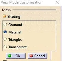
STEP 1: Changing view mode to the material.
View mode>view mode customisation>tick material>ok
STEP 2: Calling Draft Analysis.
Toolbar>Insert>Analysis>Feature Draft Analysis
STEP 3:
- Drag the compass from the draft analysis box on the tooling axis and place it properly.
- Click on locks so the compass will get locked to the tooling axis.
- Click anywhere on the component.
- Click OK.
- Analysis of the color of the failing and passing surfaces.
If a component is showing in a Green color that means our component is ready for manufacture.
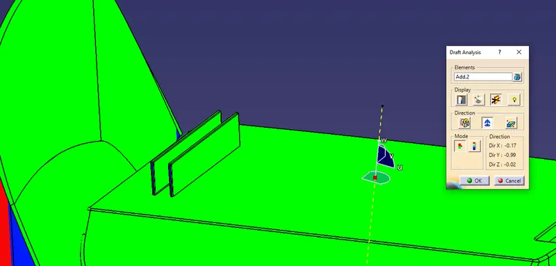
NOTE: If we find zero degree or negative degree filing color, we can fix it by changing the draft angle, sweep direction, modifying properly tooling axis, etc.
Draft Analysis for Rib formation:
The Draft Analysis command enables you to detect if the part you drafted will be easily removed. This type of analysis is performed based on color ranges identifying zones on the analyzed component where the deviation from the draft direction at any point, corresponds to specified values. This rule of thumb applies to parts with mold depths of up to 2 inches. At this size, a draft as low as 1½ degrees will allow for an easy, non-damaging release from the mold when the expected shrinkage of the thermoplastic material occurs.
It’s also important to remember that draft angles are just one component of an effectively designed injection molded piece. Design for manufacture is one of the easiest ways to improve the quality and efficiency of your injection molding process, and it never hurts to stay up to speed on all injection molding best practices.
- Checking feature draft analysis on the final part body.
- Walls of the ribs show a negative angle of 0.5 degrees because we have provided 0.5 degrees the inside draft with respect to t
CONCLUSION :
The creation of the Rib on Coin Holder has been successfully done with the guidance of design rules. It has been converted from the surface into a solid body. The tooling axis has been created according to the OEM standard.
LEARNINGS :
- Creating Ribs on the component.
- Height of Ribs.
- The thickness of Ribs.
- A draft angle of Ribs.
- Maintaining edge length on the top of Rib after the draft.
- Filleting Ribs.
- Measuring Rib Root Thickness.
- The gap between every two successive Ribs.
- Output feature of the sketch.
- Feature Draft Analysis on Ribs.