Week 9 - Attachment Feature Creation - Challenge 1
RIB ATTACHMENT CREATION- COIN HOLDER SOLD PART
Objectives:
- To study the importance of ribs in a plastic molded component
- To design ribs on the coin holder part as per design guidelines
Software used: DS CATIA P3 V5 - GENERATIVE SHAPE DESIGN, PART DESIGN WORKBENCHES
Introduction: We know that one of the basic principles of a design is to create something that is feasible for its application and at the same time using the lowest possible resources. Our parts must be structurally stable, rigid and also must include less possible material. Ribs are a structural component that helps to give strength to plastic components by utilizing a minimal amount of material.
Other features of ribs:
- Locating and arresting components of an assembly
- Providing alignment in mating parts
- Acting as stops or guides of mating parts.
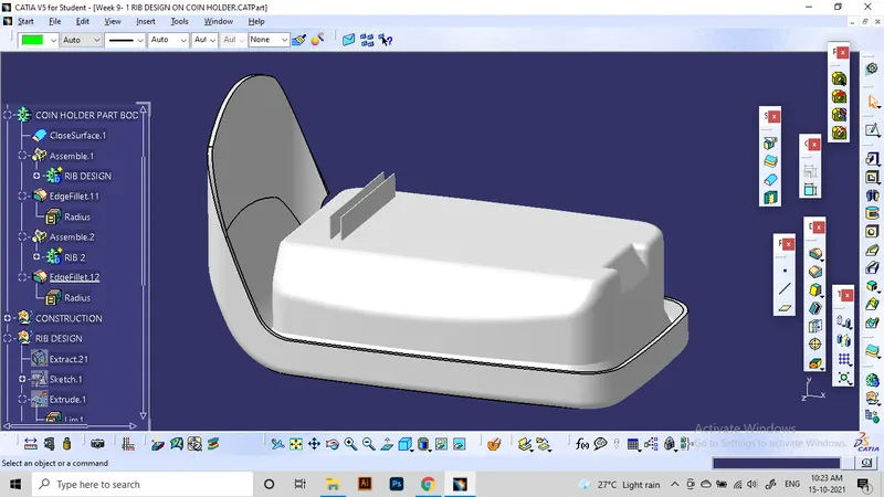
In this project, I'm making rib structures on the bottom side of the previously made coin holder part.
Design principle:
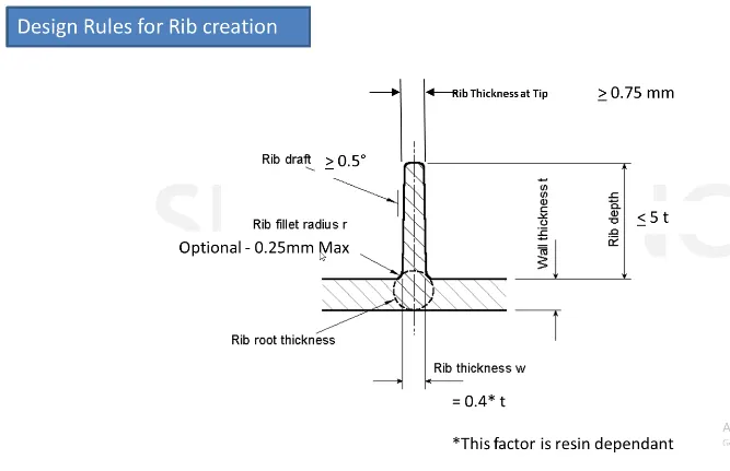
Rib creation on coin holder:
First, we need the bottom side of the part extracted as plane. This plane is used for creating a sketch of a line that will be used for rib creation.
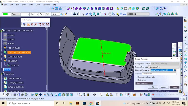
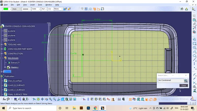
The line is then extracted along the tooling axis for the distance that works as height of the rib. From our design principle,
Height of rib <= 5 x thickness of solid part(ie, 2.5 mm) = 12.5 mm
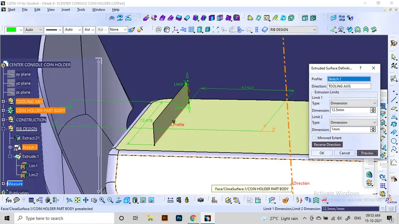
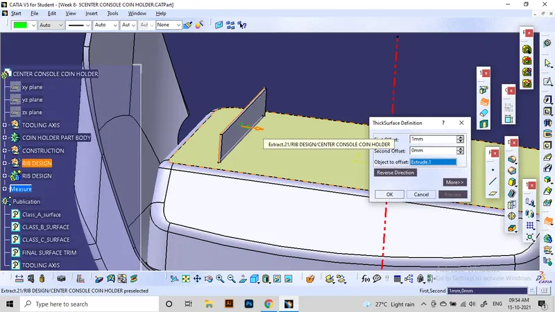
Next, we need to thicken the extracted surface in part workbench.
Maximum thickness of the rib = 0.4 x Thickness of solidpart= 0.4 x 2.5 = 1mm
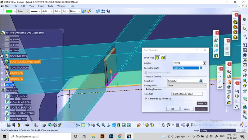
Applying the draft angles at 4 sides of the rib using the draft tool for an angle of 0.5 degrees.
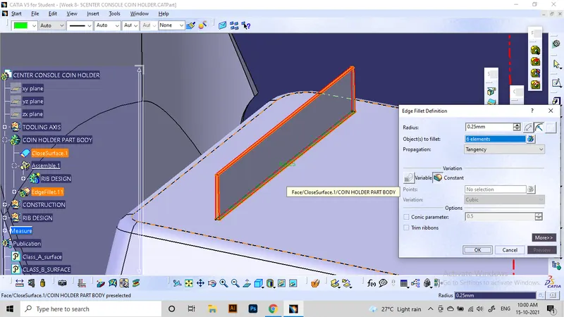
Later fillet all edges of the rib. Sharp edges might create unfilled cavities after molding. All edges must be filleted at a maximum angle of 0.25 degrees.
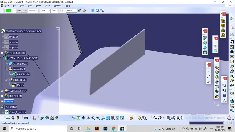
For analyzing the fillet cross-section with the part, we can use the intersection tool. Here is the resulted section view:
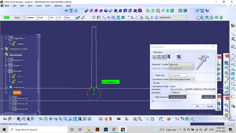
The diameter of the tritangent circle shows the rib root thickness.
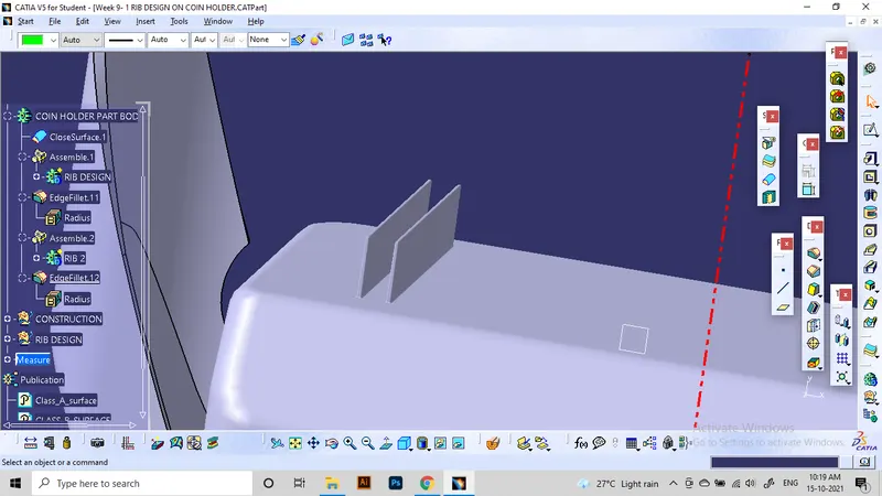
Using a similar method, we can construct more ribs according to the need. Spacing between ribs can be calculated considering the ratio between the height of rib to the gap ratio. 3:1 is accepted for plastic components. the height of the rib is 3 times the spacing between ribs.
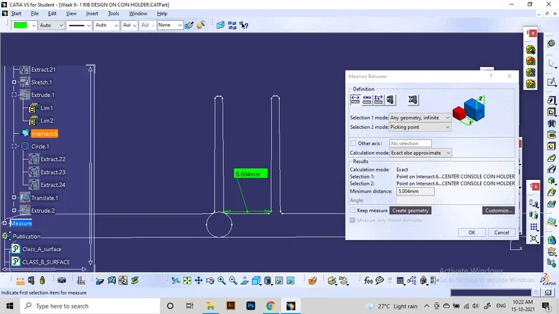
here, the height of rib= 12.5 mm. so the spacing will be 4.2 mm.
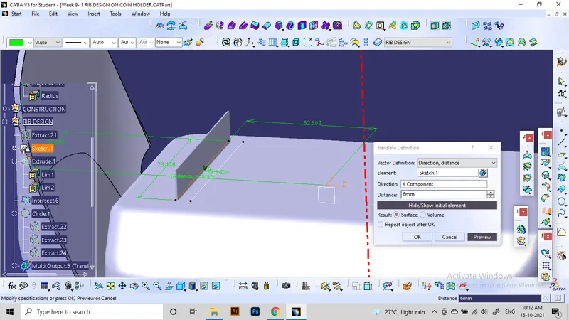
This spacing is between the imaginary centre lines passing through the ribs. So when considering the thickness also, we can make the sketch at an approximate distance of 6mm from the previous sketch.
Conclusion: Studied the applications of ribs in plastic components and their advantages. Learned to design ribs on 3d surfaces using proper OEM standards.