Week 9 - Attachment Feature Creation - Challenge 1
RIB DESIGN
OBJECTIVE
- To design a rib by applying all design constraints.
- To design multiple ribs by applying design constraints.
- To perform draft analysis.
INTRODUCTION
Rib is a design feature that helps in strengthening the plastic components. Generally to increase stiffness and strength the component’s thickness is increased. By doing it might end up in sinking, warping, and other defects etc. so instead of increasing the thickness we can add some attachment features to compensate those strength loss. This method much economical. Ribs also facilitates for locating and arresting components in assembly, provides alignment, etc.
RIB DESIGN RULES
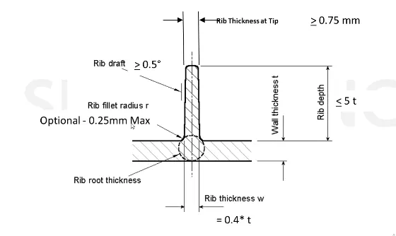
- THICKNESS (W)
Rib thickness at base should be 0.4 or 0.5 times the wall thickness. The minimum tip thickness of rib is 0.75mm. Very thin rib results in poor mold filling ability.
W = 0.4 * t mm
- FILLET RADIUS
Optimal fillet radius is 0.25mm.
- HEIGHT
Rib height should be 5 times the wall thickness.
- ROOT THICKNESS
The root thickness has to be greater than or equal to wall thickness.
- LOCATION
Ribs can be spaced with each other based on height/width ratio.
3:1 for steel
2:1 is preferred all times.
- DRAFT
The minimum draft for ribs is 0.5 degrees.
RIB DESIGN
- Importing the coin holder component into CATIA interface.
- Extract the surface on which the rib is to be designed.
- Draw a line and extrude it to create a surface.
- Inset a new body
- Thicken the surface by 1mm.
From design rule,
W = 0.4 * t
= 0. * 2.5
= 1mm
- Change the extruded height to 12.5mm
From design rule,
H = 5 * t
= 5 * 2.5
= 12.5mm
- Draft is given of about 0.5 degrees.
From design rule,
The minimum drat angle for ribs is +/- 0.5 degrees.
- All the edges are given 0.25mm maximum fillet radius.
- Check the root thickness. It is 2.68mm.
- Now creating another rib spaced at 5mm.
From design rule,
As per 3:1 ratio
Height /Width = 3/1
Width = 12.5/3
Width = 4.166mm
That is approximately 5mm.
10. Repeat the same procedure to create another rib.
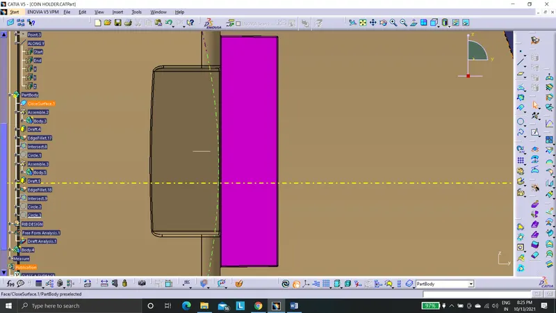
FRONT VIEW
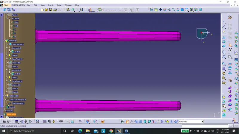
SIDE VIEW
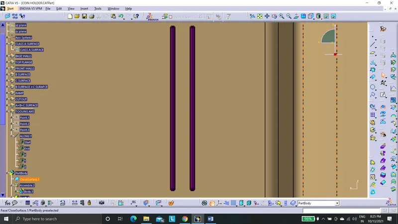
TOP VIEW
CROSS SECTION PROFILE
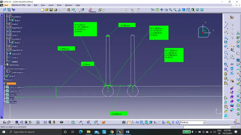
In which all the values are measured and vaerified.
DRAFT ANALYSIS
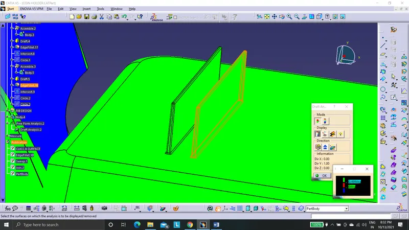
The draft analysis shows that the rib is manufacturable with respect to the tooling axis.