Week 9 - Attachment Feature Creation - Challenge 1
INTRODUCTION
Ribs are thin, wall-like features typically designed into the geometry of a part to add internal support to walls or other features. They provide a means to economical stiffness and strength in molded parts without increasing overall thickness.
OBJECTIVE
To create the rib for the Centre console coin holder considering all the design rules
METHODOLOGY
- The first thing we do after getting the component is creating a tooling axis for the component.
- Then we do the draft analysis to check if the tooling axis is correct.
- Then we start creating ribs for the component according to the design rules.
- After creating the ribs we again do the draft analysis to check if the created ribs satisfies the draft.
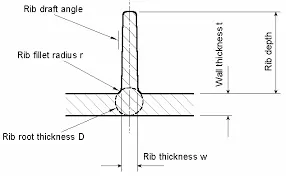
Design Rules-
- Thickness-
w = 0.4*t
- Measure the base thickness of the rib at tangent of radius if radii are modelled in.
- The larger the area at the base of the rib, the more retained heat.
- The retained heat causes more shrinkage, which causes sink.
- Draft-
0.5 degree per side minimum.
Allows the rib to release from the mold.
- Thickness at top-
Minimum thickness at Rib tip – 0.75mm
- Optional radius-
Optional rib fillet radius- 0.25mm maximum.
- Height-
Rib height ≤ 5 x nominal wall thickness
- Spacing-
Ribs should be spaced so that the steel between is at a height/width ratio
- 3:1 steel
- 2;1 preferred
Draft analysis-
- Draft analysis is performed on components where the ejection of materials happen after the material is made inside the tools.
Tool Axis:
- For the tooling axis we first inspect by taking a section and then decide which direction would be better for the tool axis.
- Then we create a point at the centre of the base and create an axis system. Then we intersect the surface A with the YZ plane.
- With the intersection we get what we observe is that the side walls of the class A surface are parallel with the vertical axis i.e. there is 0° degree angle between them.
- But since it’s a class A surface we have to go the same design since we do not have the authority to change the class A surface design. So we have to go with this draft angle inself.
- We create a vertical line along the point created and the vertical axis and this will be our main tooling axis.
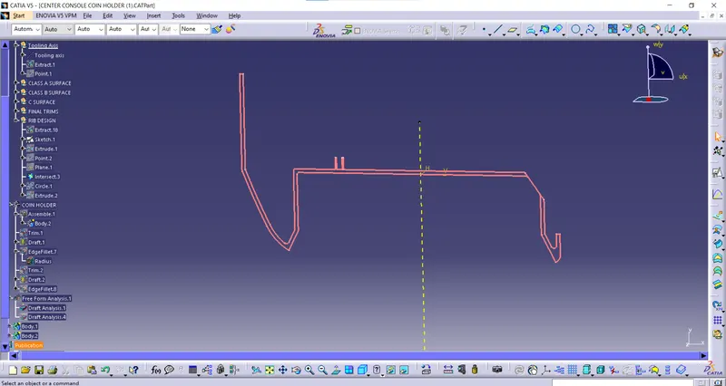
Rib creation:
- We create a sketch and in that we create a line which is iso constrained.
- Then we extrude the surface upto 12.5mm according to the design rule which is 2.5*5.
- Then we thicken the surface of the rib by using the thick surface option. We thicken it by 1mm which according to the design rule is 0.4*2.5.
- We then give a draft of 0.5° to the ribs with respect to the tooling axis.
- We then give a fillet of 0.25mm to all the edges and after this final step we assemble it with the coin holder body.
- After deciding all the height and width of the rib we carry on to create another rib. The spacing between the two ribs is decided with respect to the design rule. We modify the sketch and offset the line on that sketch by 6mm considering the thickness of the rib and the design rule.
Then we follow the same steps to create another rib.
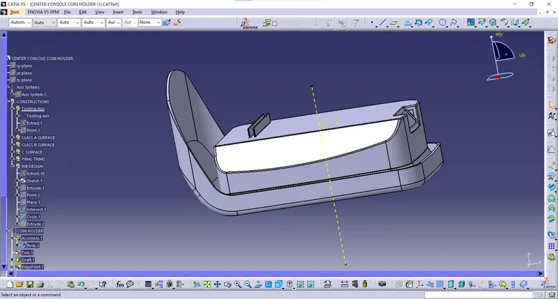
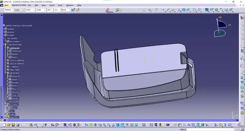
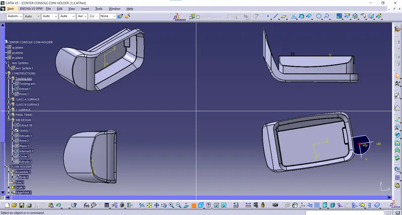
Draft analysis of the component -
- Before drafting we have to make sure that in the view mode it is selected to the materials.
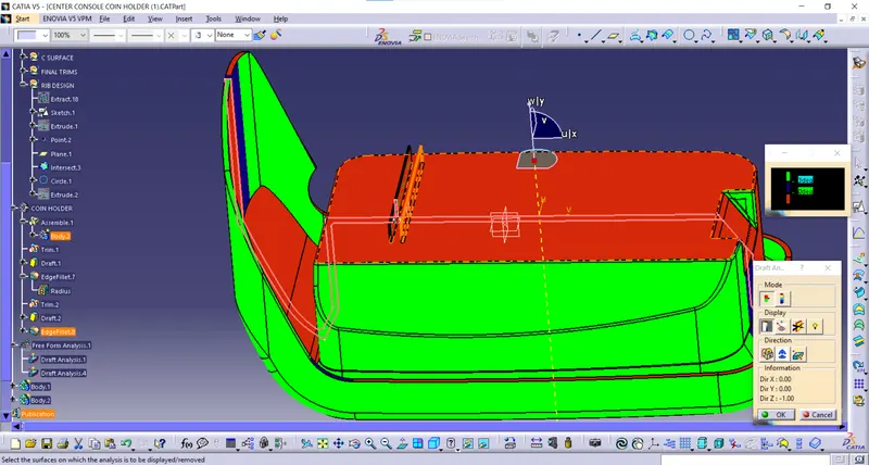
- After selecting the feature draft analysis tool we drag the compass from its position to the tool axis. Then lock the compass. After that select anywhere on the component and it will give you the result.
- We change the minimum draft for the component to 3°.
- We can use the running point option to check the angle of the component.
- We can even modify the colour according to our preference.
CONCLUSION
- With this we got to learn about the rib design and all the rules applied while creating and designing a rib.