Week 9 - Attachment Feature Creation - Challenge 1
PART I: Rib Design
1. Iso-constrained Sketches
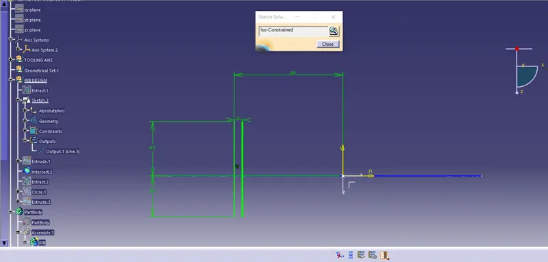
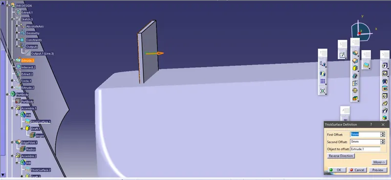
The above line is extruded along the direciton of tooling axis, and provided the thickness of 1mm
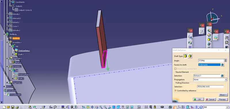
Draft angle
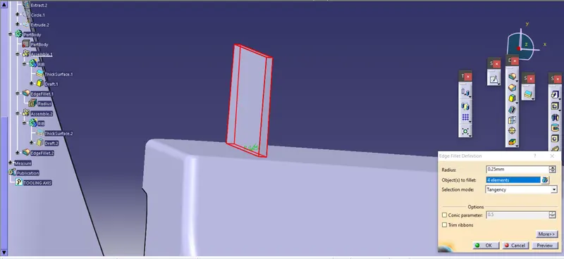
Edge Fillet of 0.25mm
In a similar way second Rib was created and spaced at 5mm
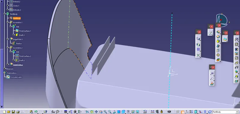
Rib Creation Report:
Rib design has has to follow the guidelines provided
1. Draft: A draft of 0.5 degree is provided on the both the sides of rib to ensure easy removal from the mold
2. Thickness: It should be 40% of the wall thickness of the component
3. Rib height: It should be five times of wall thickness of the component
4. Rib Spacing: It should follow height to width ration of 3:1, while 2:1 is preferred.
5. Minimum thickness at the Rib: It should be 0.75 mm
6. Fillet: It should be of 0.25 mm
7. Width: It should be 0.4 times of the thickness
PART II: Rib thickness analysis
A rib thickness analysis was performed by measuring all the geometric parameters and to ensure they meet the provided design guidelines.
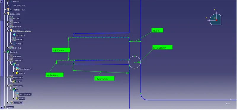
All the views of Rib design
1. Isometric View
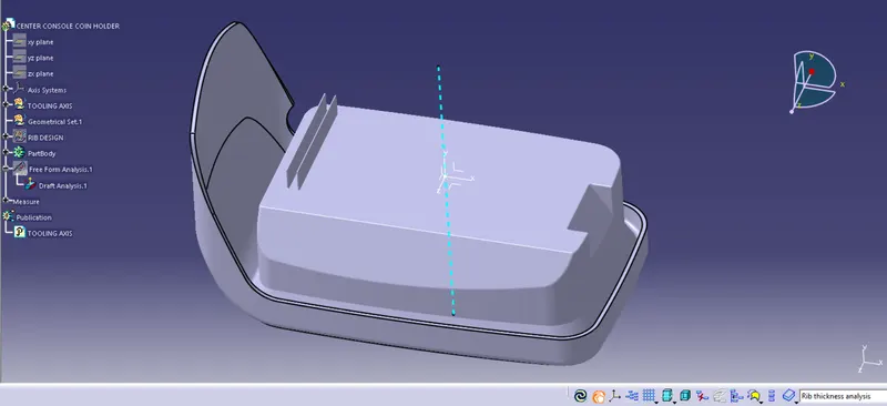
2. Front View
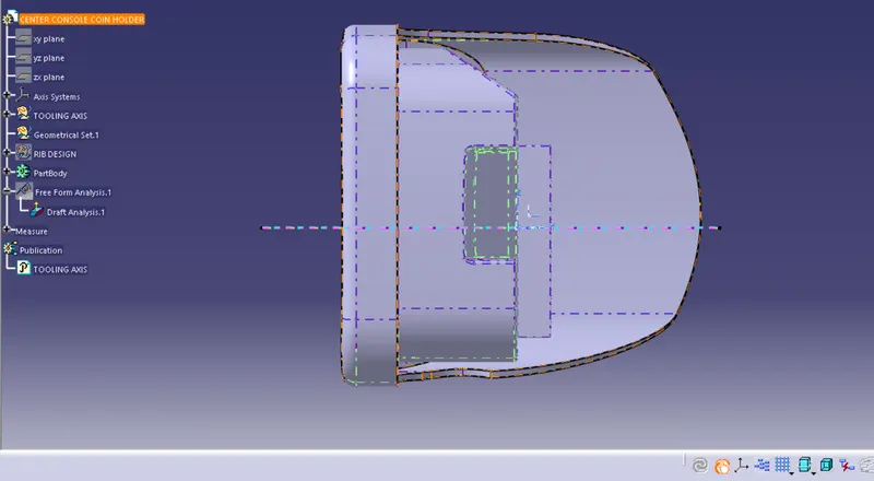
3. Top View
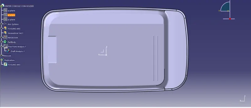
4. Side View
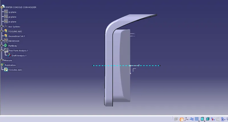
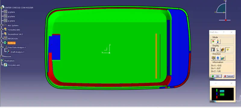
PART III: Draft Analysis
1. Isometric View
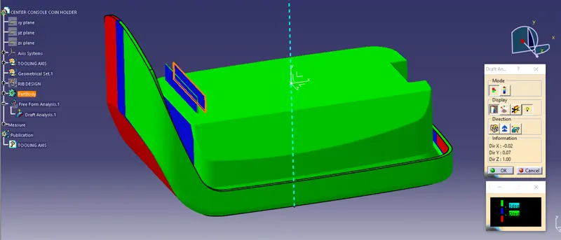
2. Front View
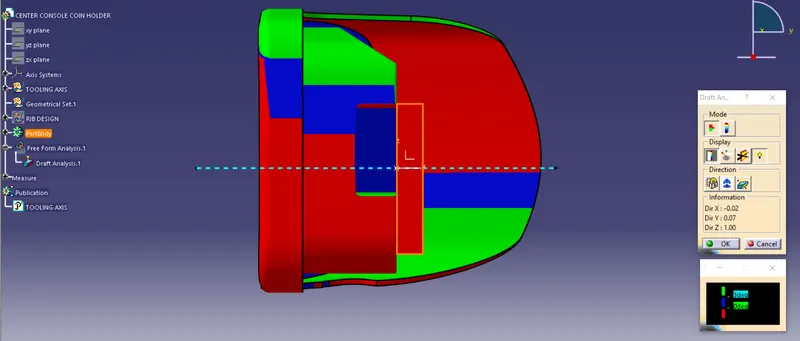
3. Top View
4. Side View
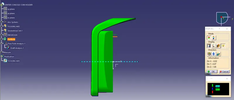
Draft analysis report:
- The green color represents angle of surface with respect to tooling axis being greater than 3 degrees.
- The blue color represents angle between 0 and 2 degrees.
- The red color represnts angle lesser than 0 degrees. It represnets errorneous draft angle that needs to be corrected.