Week 9 - Attachment Feature Creation - Challenge 1
Procedure To Create the Ribs for Coin Holder
Step -1: - to Create the ribs or any other features first step is to create the tooling axis of the component and start adding the extra features for any component.
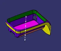
Step -2: - To create the tooling axis check component in all 3 Axis the component. In which direction component can clear all the features in the tooling axis. In my case, according to class A, the tool Y-axis is my tooling axis. Due to the component side walls are having 900with respect to the base I took the centerline perpendicular to the plane. That covers all the sides of the component. Insert all the tooling axis features into a geometrical set and name as Tooling Axis. to set the tooling axis an insert a geometrical set and extract the base and mark a point use the point and draw a line that is perpendicular to the base plane. And name the plane as the tooling axis.
Note: - there are Guidelines for Design of Ribs
- Thickness
- Height
- Location
- Quality
- Manufacturability
These are the points to be noted when design 0n Ribs.
Step -3: - To start the rib design insert a geometrical set name it as RIB Design and extract the face where the rib is to be located and create the positioned sketch take the face as the plane and select the point which is used in the tooling direction. Then start sketching on the plane draw a line with the required dimension of the rib and make an iso-constrain sketch and extract the sketch based on the rib design Rules the height (depth of rib) of the Rib is 5t(t=thickness of the component)the thickness of the component is 2.5mm
`therefore`5x2.5=12.5mm
Extract the line up to 12.5mm at the top and below 1mm to merge with the component.
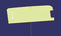
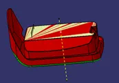
Step -4: - The next step is to add the thickness of the Rib for that we are having a formula of 40% of the thickness of the component. After the extrude the line fo to the part workbench and add thickness for the surface up to 1mm
`therefore`0.4x2.5=1mm
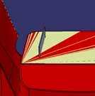
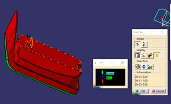
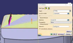
Step -5: - Next step is to add the drafts for the rib Drafts is used to easy ejection of the component for that the minimum draft angle for the rib is 0.5o is required.to add the draft select the draft tool and select the to be draft and select the perpendicular plane or neutral plane for the draft and select the tooling axis for the direction of pull.
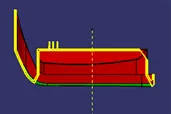
Step -6: - After adding the Draft of the component there check all the parameters for the rib by using the intersect option. For intercepting the component we need to perform the Boolean operation(add the Rib to the main component ) create a plane that is parallel to the XY plane at the point of the neutral axis and select the intercept command and select the main component part file and select the plane the intercept of the component was formed
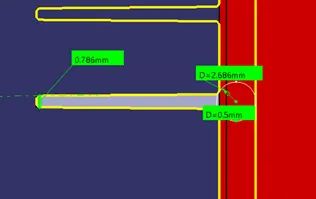
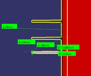
Step -7: - Measure the Rib tip thickness which is more than . and main root thickness of the Rib and thickness of the Rib and drafts of the rib if every measurement according to the guidelines add fillets for the component which is 0.25mm
Step -8: - For the next step add the extra rib on the same component edit the sketch add an extra line on the sketch with a distance of 3:1 0r 2:1 I created 2models the first rib of having 3:1 which is 3 /1 =3 the total height of the rib divided by the result which is 3 and repeat the same process for the next rib
`therefore`12.5 `div` 3=4.1666 (4.20) mm
The distance between the ribs is more than 4.2mm.
Step -9: - And the same process for the 2:1 distance rib also. Check the dimension of the ribs and do the Draft analysis of the component weather the tooling direction clears the ribs or not we can have a clear view of the component
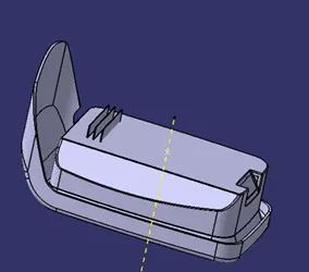
Step -10: - the next step is the Draft analysis of the component for that go to insets and Analysis to Feature draft analysis. Draft analysis interface will open and use compose option and select the UCS and fix the axis to the component. And check the draft position correct or not if it is in the wrong direction change to inverse the draft direction. If any changes are required for the changes in the walls Draft angle adjust the sketch to get the perfect Draft angle.