Week 9 - Attachment Feature Creation - Challenge 1
Objective: To design rib according to the given considerations and to perform draft analysis on the final component i.e.,. coin holder.
Procedure:
1. To perform draft analysis, tooling axis must be created which can be created by extracting the base surface of the coin holder and by selecting the point command create a point on the surface which is extracted. Since the side walls donot have any draft provided by the styling team, so directly select the line command and create a line along Y-direction and name it as tooling axis and publish the tooling axis for the quick glance.
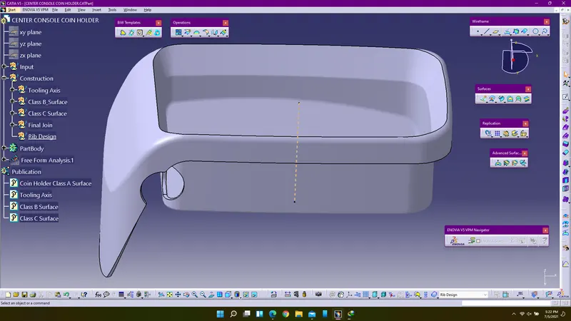
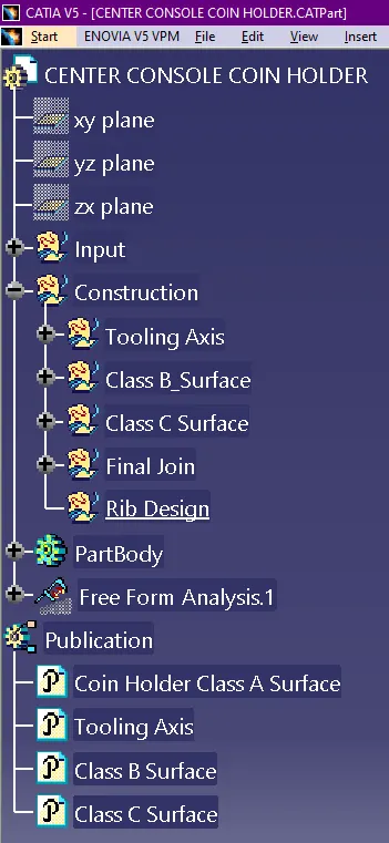
2. Next step is to create rib on the base surface which is on the B-surface, since B-surface is the engineering surface all the fittings will be provided on it. A-surface is said to be asthetic surface no weldings or any engineering operations were not performed on the A-surface. To create rib enter into the generative shape design workbench and insert a new geometrical set and name it as rib design under construction.
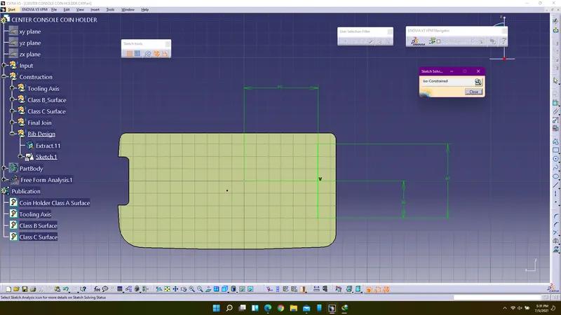
3. Select the base of the coin holder (B-surface) and extract the surface using extract command and create a sketch over it.
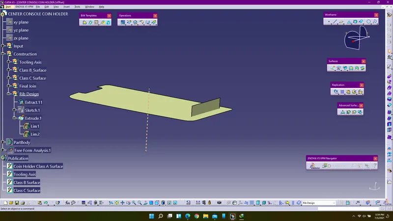
4. Extrude the sketch using tooling axis direction and consider the depth of rib to be as 5*wall thickness. Enter into the part design workbench and use thick surface command to create a solid, the thickness of the rib must be 0.4*wall thickness.
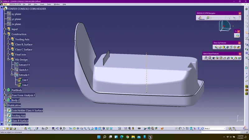
5. Add the thicken surface to the coin holder using add boolean operation. Use draft command to create draft for all the faces of the thicken surface. Consider the draft angle as greater than or equal to 0.5mm. Select the base as a natural element and pulling direction as tooling axis.
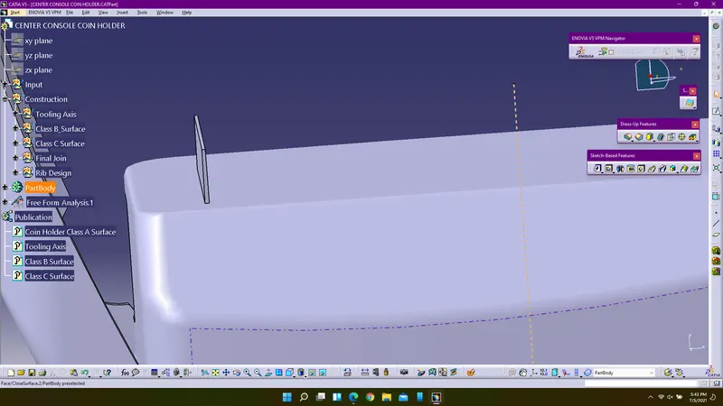
6. Create the fillets on the rib and the radius for creating the fillets is 0.25mm.
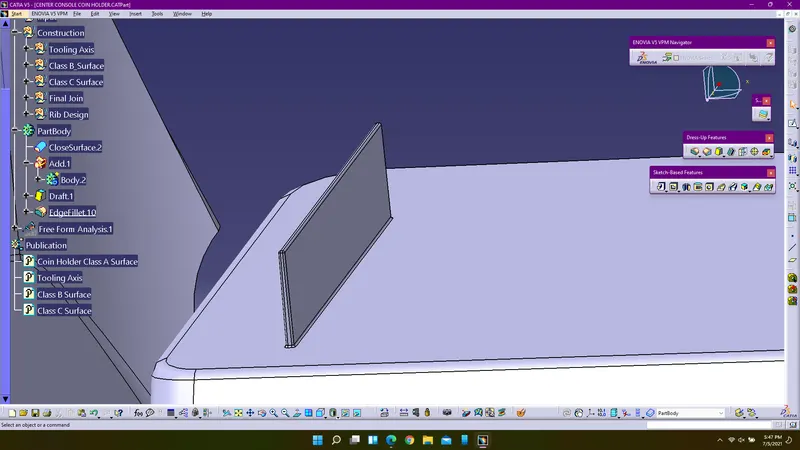
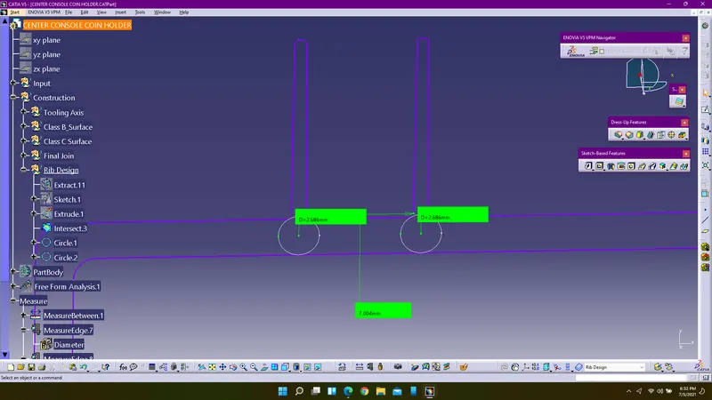
7. To create a next rib on the base there must be atleast 4.1667mm gap between the ribs if the material is steel. In our case height to width ratio must be less than 2, so the gap between the rib must be atleast 6.25 to 8mm. I am considering Y/X<2.
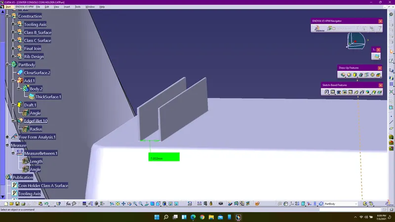
8. Create intersection curve by entering into the generative shape design workbench.
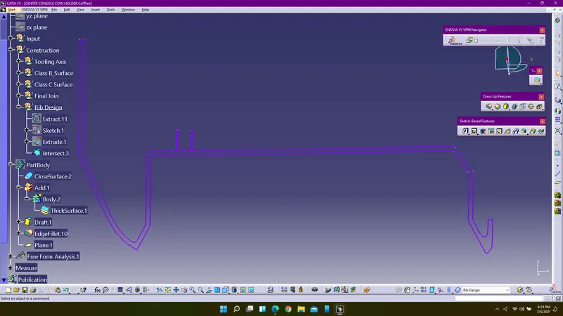
9. Create a tritangent circle using circle command and mesure the diameter of rib root thickness.
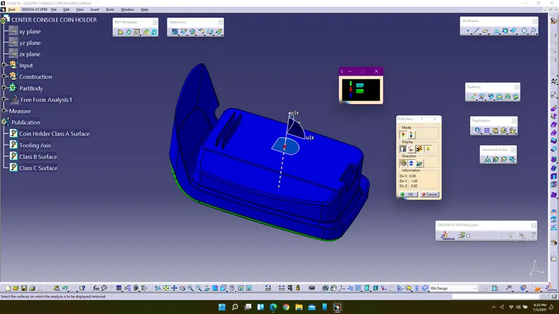
10. Perform draft analysis for the final component.
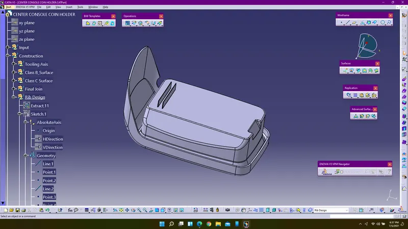
Feature Tree Diagram:
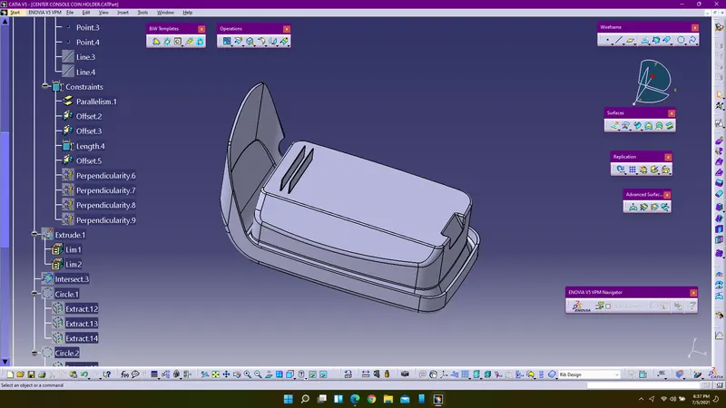
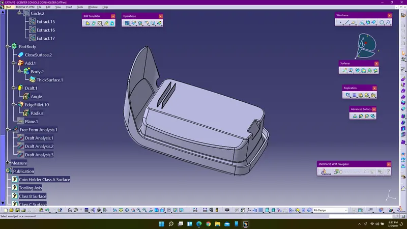
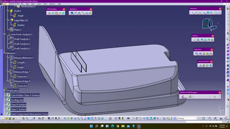
Conclusion:
Ribs were created according to the given considerations and provided the measurements of it and performed draft analysis for the final component.