Week 9 - Attachment Feature Creation - Challenge 1
Rib Design
Ribs are created in the product to provide support and strength to the designated part regions. Ribs are the alternative to improve the strength of the product without increasing the thickness, these are usually created and assembled on the B surface of the part. The ribs can be added to the part before or after the molding proccess.
Usually while manufacturing a product the designed products may be prone to certain injection molding defects such as warping, Flash, sink marks, vaccuum voids, weld lines etc, Inorder to prevent these defects certain design considerations has to be followed while designing the ribs;
1. designed with half the wall thickness value
2. distance between the ribs should be atleast twice the wall thickness
3. Ribs are deisned with atlest 60% of the joining wall thickness to prevent sink marks
4. Minimum Draft of .5 deg is acceptable
5. Ratio between the rib height to the spacing between two ribs should be maintaned to a ratio of 2:1 and the maximum permisible ratio is 3:1
Design Approach
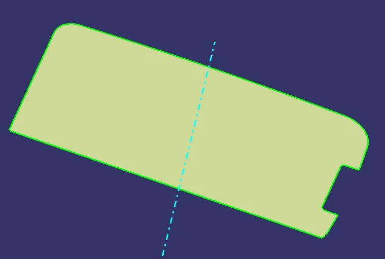
The base of the model is extracted
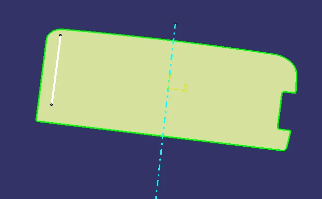
Using Positioned sketch a line with 70mm is created over the extract and
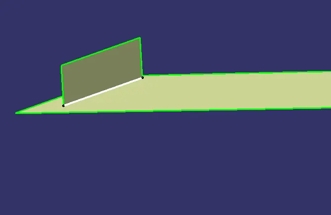
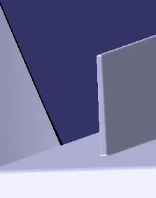
Once the line is created the line is extruded with a dimension of 12.5mm height (5 times 2.5mm thickness) with respect to the tooling axis.
Once the extrude is created the pert body tool is selected and the surface is thicken to 1 mm (0.4 times 2.5 mm thickness). after that a 0.5 deg draft is given to the rib and an edge fillet of 0.25mm is provided.
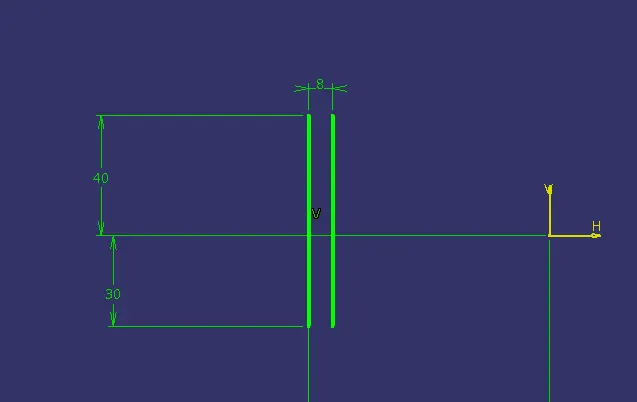
A second line is created at the base sketch for the creation of second rib at a distance of 8mm
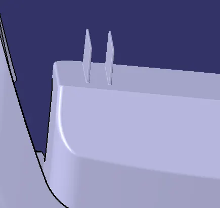
The similar step is followed to create the second rib
Once the ribas are created a plane is created parallel to the tooling axis and using Intersection tool.
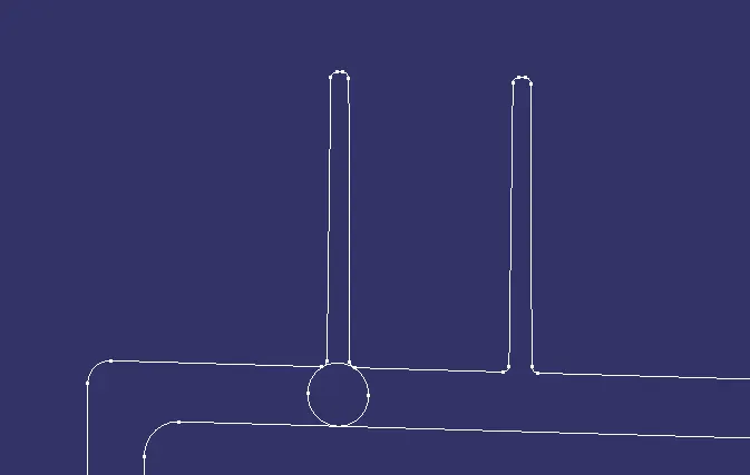
A Tri tangent circle is created at the rib root region, after this process they are measured.
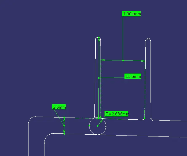
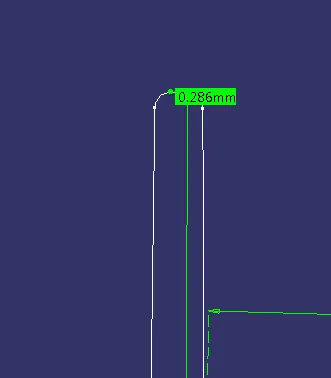
The distance between the two ribs is taken as 7mm, here 2:1 ratio is followed, (12.5/2= 6.25).
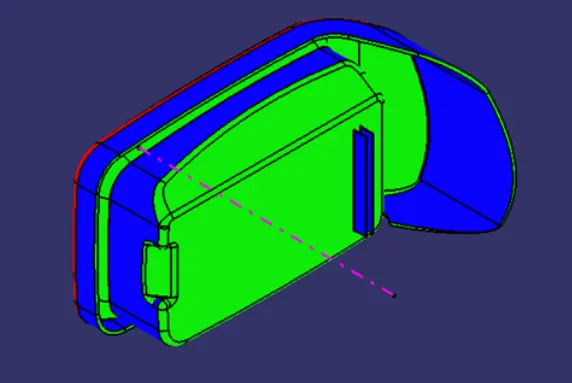
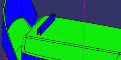
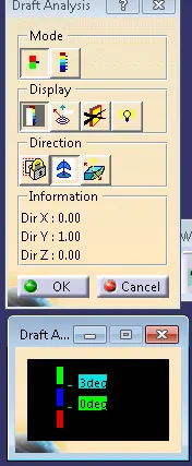
Once the ribs are created they are assembled with the coin holoder part body. After that draft analysis is done on the body
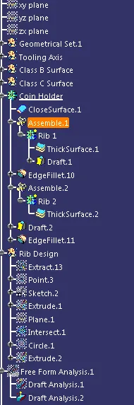
Tree Stucture: