Week 9:- 2D Detailing Challenge
1. What are the Drawing templates?
Drawing template:- It stores document settings that can be used again and again. This can include a sheet format. Here are some examples of these settings:
- Drawing Document Properties: Drafting Standards, Units, Font style, sizes, etc.
- Custom Properties
- Tree Display
- Predefined Views
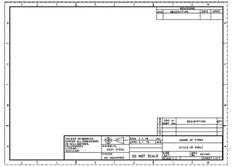
Fig 01:- Drawing Template
The drawing Template consists of
Title Block:- It is normally placed in the bottom right of the drawing frame, and it should contain the following information:
- the name of the company or organization
- the title of the drawing
- the drawing number, which is generally a unique filing identifier
- the scale
- the drawing size
- the angle of projection used, either first or third, is generally shown symbolically
- the signature or initials of the draftsman, checker, approving officer, and issuing officer, with the respective dates
- the material of the part
- the revision number
- the sheet number for multi-sheet drawings
- Other information as required (tolerances, surface finish, etc.)
Fig 02:- Title Block
Revision Table:- A revision table is normally located in the upper right of the drawing frame. All modifications to the drawing should be documented there.

Fig 03:- Revision Table
Material or Parts List (Bill of Materials):- If the drawing contains several parts or an assembly drawing, a tabulated parts list is added to the drawing. The bill of materials is usually placed at the bottom right of the drawing frame, just above
the title block.
The bill of materials should give the following information:
- the part number
- the part name
- the quantity required
- material specifications
- the drawing number of each part
- other applicable information
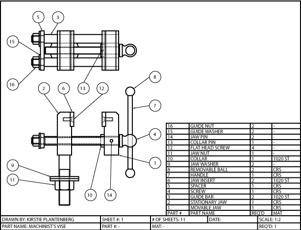
Fig 04:- Bill of Materials
Zoning:- A drawing may be divided up into a grid using letters and numbers. When zoning is used it is located inside the drawing frame. Zoning is usually used for large-size drawing sheets where it allows easy references to various parts of the drawing by referencing a coordinate such as B4.
Fig 05:- Zones
Notes:- Information other than pictorial views and dimensions necessary for completing a drawing is classified as “notes”. Notes are usually placed in the drawing sheet's lower left corner and numbered consecutively downward.
Some examples of the notes used in working drawings are as follows:
- Dimension Notes ALL DIMENSIONS APPLY AFTER SURFACE TREATMENT.
- Heat Treating Notes HEAT TREAT IN ACCORDANCE WITH standard-XXX TO XXX-hardness
- Joining Method Notes (welding, brazing, etc.) FUSION WELD IN ACCORDANCE WITH standard-XXX
- Plating and Coating Notes CADMIUM PLATE IN ACCORDANCE WITH standardXXX
- Surface Preparation Notes SURFACE TO BE CLEANED AND POLISHED FOR VACUUM USE.
- Testing and Inspection Notes RADIOGRAPHIC INSPECTION OF ALL WELDS IN ACCORDANCE WITH standard-XXX
- Threaded Inserts — Cleaning and Installation Notes TIGHTENING TORQUE OF THREADED FASTENERS SHOULD BE AS LISTED IN TORQUE TABLE
- Miscellaneous Notes PLACE IN BAG AFTER FINAL ELECTROPOLISHING.
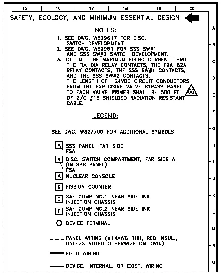
Fig 06:- Notes
2. What do you understand by Angle of projection?
The angle at which the observer looks at an object and draws it in 2D from 3D from a real object to paper is called the angle of projection.
Parallel projection is used to generate drawing which is used for manufacturing the part. The angle of projection is usually perpendicular to the object. A plane is an imaginary surface on which pictures are drawn. Usually, a minimum of 3 views of the object are required to be able to present all the dimensions required for manufacturing.
When two planes one horizontal and one vertical are considered principal planes, These planes are placed such that they form 4 quadrants. When the object is placed in 1 quadrant it is called first angle projection, i.e., the plane is behind the object. When an object is placed in the 3rd quadrant, it is called 3rd angle projection, i.e., the object is behind the plane.
In orthographic projection, there are the following views:
- Front view
- Top view
- Back view
- Bottom view
- Right-side view
- Left side view
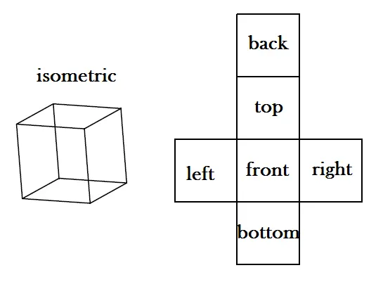
Fig 07:- Angle of projection
Orthographic drawing:
- The front view and top view always form over/under each other.
- The top view shows the length and breadth of the object.
- The side view shows the length and height of the object.
- The front view shows the length and height of an object.
- The side view is always beside the front view.
- The hidden detail of an object is shown as a dotted line.
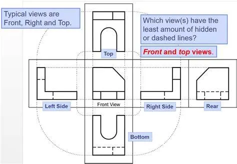
Fig 08:- Angle of projection
Selecting the view:
- The most detailed view should be selected.
- The selection of views with maximum detail should be made.
- The selection of views with more internal details should be made.
- The selection of view of required details should be made.
3. What are the First angle and third-angle projections? and why can't we use the 2nd and 4th angle of projection?
Orthographic views allow us to represent a 3D object in 2D on a drawing. Orthographic views can show us an object viewed from each direction. How the views are laid out on a drawing depends on whether 3rd angle or 1st angle projection is being used.
First Angle Projection :
In the first angle projection, the object is placed in the 1st quadrant. The object is positioned at the front of a vertical plane and top of the horizontal plane. First angle projection is widely used in India and European countries. The object is placed between the observer and projection planes. The plane of projection is taken solid in 1st angle projection.
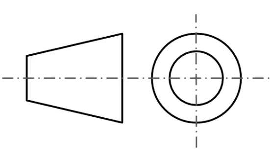
Fig 09:- 1st Angle of projection
Third Angle Projection :
In the third angle projection, the object is placed in the third quadrant. The object is placed behind the vertical planes and at the bottom of the horizontal plane. Third-angle projection is widely used in the United States. The projection planes come between the object and the observer. The plane of projection is taken as transparent in 3rd angle projection.
Symbol –
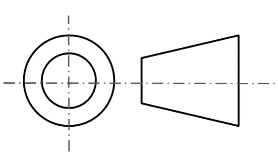
Fig 10:- 3rd Angle of projection
Differences between 1st & 3rd angle of projection
| Parameter | First Angle Projection | Third Angle Projection |
| Method of Projection | When you divide a plane into four quadrants, you can place any object in the first quadrant in a first angle projection schema. | When you divide a plane into four quadrants, you can place any object in the third quadrant in a third-angle projection schema. |
| Placement of Objects | It places the object between the observer and the plane of projection for the first angle projection. | It places the object between the observer and the object for the third angle projection. |
| The sequence of views in | n the first angle projection schema, the views come in the following sequence- top left, then clockwise, the Right view, the Front view, and the Top view. | In the third angle projection schema, the top view sits at the top of the front view, and the right view sits on the right side of the front view. |
| State of Projection Plane | You can take the plane of projection to be opaque (solid) at the first angle of projection. | You can take the plane of projection to be transparent at the third angle of projection. |
| Uses | Widely used in India, Europe, and Canada. | Widely used in Australia and the United States. |
| Identification | You can identify a drawing of the First Angle Projection by the symbol of the first angle projection. This symbol of the angle of projection typically appears near the Title block in the angle of the projection block. | You can identify a drawing of the Third Angle Projection by the symbol of the third angle projection. This symbol of the angle of projection typically appears near the Title block in the angle of the projection block. |
Fig 11:- Differences between 1st & 3rd angle of projection
Why can't we use the 2nd and 4th angles of projection?
As per the declared rule of projection, when the horizontal plane is rotated 90° in a clockwise direction, the top and front views will overlap. These overlapping projection views create confusion in the drawing. Therefore the second and fourth angle projection systems are not used in our country.
4. What is GD&T? What are the benefits of GD&T?
Geometric Dimensioning and Tolerancing (GD&T) is a design approach and manufacturing mechanism that helps engineers and designers communicate how to bring a part design to life. When documented correctly using GD&T, it is possible to build a part that exactly matches its on-paper plans.
The drawing is the controlling document that ensures the vendor is creating precisely what the customer’s design requires. Machinists and quality engineers will use GD&T, print dimensions, and drawing notes to develop a manufacturing process and inspection methodology that will construct high-precision components matching the designer’s original vision. Proper print detailing will also help with measurement correlation to aid in the communication between customer and vendor.
GD&T uses symbolic language to indicate how significantly part features can deviate from the geometries listed in the design model. This language contains all relevant details involved in fabrication, including dimensions, tolerances, definitions, rules, and symbols that communicate a component’s functional requirements.
Benefits of GD&T
- Saving Money — GD&T enhances design accuracy by allowing for appropriate tolerances that maximize production. The process provides extra or bonus tolerances for many projects, further increasing cost-effectiveness.
- Ensuring Dimensional and Tolerance Requirements — A thorough GD&T process guarantees accurate fulfillment of all dimensional and tolerance specifications by explicitly stating all design requirements.
- Assisting Digital Design Methods —Clear, concise GD&T data is readily adaptable to digital design programs, including nearly universally used 2D and 3D CAD files.
- Offering Uniformity and Convenience — As a single, consistent language, GD&T reduces guesswork and interpretation while ensuring consistent geometries across design and manufacturing.
- Providing Accurate Communication — Today’s intricate designs demand the most accurate and reliable communication. GD&T enables designers, manufacturers, and inspectors to communicate clearly with one another, saving time and making the process more efficient.
- Simple communication. GD&T allows you to convey substantial information about your part’s design using a relatively small number of letters, numbers, and symbols. No long paragraphs of explanation are necessary! The ability to communicate efficiently reduces back and forth between you and the contract manufacturing service you are working with.
- Accurate production. Since GD&T is such a precisely articulated system of language, it minimizes ambiguity in the description of a part's design. As a result, you can be confident that your part will be manufactured with the highest degree of accuracy and work as intended in the field.
- Known tolerances. GD&T gives manufacturers a clear understanding of the tolerances for a specific part. It provides the maximum amount of tolerance for the part to function properly, reducing part complexity so that you aren’t overspending for a minimum tolerance you may not need.
- Universal language. You may find yourself in a situation where you want to work with a contract machining company in another country with a spoken language that is different from yours. Great news! GD&T is a universal language widely accepted across the world, thereby eliminating frustrating language barriers for overseas production.
- Precise assemblies. If you have two mating parts that need to come together in an assembly, GD&T is an excellent way to communicate how this interfacing can best take place. In these situations, GD&T depicts the tolerances of each part so that manufacturers can easily tell if a measurement is off and adjust accordingly.
5. Explain all the symbols used in GD&T?
- Removes ambiguity by applying universally accepted symbols and syntax.
- Uses datums and datum systems to define dimensional requirements concerning part interfaces.
- Specifies dimensions and related tolerances based on functional relationships.
- Expresses dimensional tolerance requirements using methods that decrease tolerance accumulation.
- Provides information that can be used to control tooling and assembly interfaces.
GD&T Symbols
GD&T is feature-based, with each feature specified by different controls. GD&T symbols fall into five groups:
-
Form controls specify the shape of features, including:
-
Straightness is divided into line element straightness and axis straightness.
-
Flatness means straightness in multiple dimensions, measured between the highest and lowest points on a surface.
-
Circularity or roundness can be described as straightness bent into a circle.
-
Cylindricity is flatness bent into a barrel. It includes straightness, roundness, and taper, which makes it expensive to inspect.
-
-
Profile controls describe the three-dimensional tolerance zone around a surface:
-
Line Profile compares a two-dimensional cross-section to an ideal shape. The tolerance zone is defined by two offset curves unless otherwise specified.
-
The surface Profile creates two offset surfaces between which the feature surface must fall. This is a complex control typically measured with a CMM.
-
-
Orientation controls concern dimensions that vary at angles, including:
-
Angularity is flatness at an angle to a datum and is also determined through two reference planes spaced the tolerance value apart.
-
Perpendicularity means flatness at 90 degrees to a datum. It specifies two perfect planes the feature plane must lie in between.
-
Parallelism means straightness at a distance. Parallelism for axes can be defined by defining a cylindrical tolerance zone by placing a diameter symbol in front of the tolerance value.
-
-
Location controls define feature locations using linear dimensions:
-
The position is the location of features relative to one another or datums and is the most used control.
-
Concentricity compares the location of a feature axis to the datum axis.
-
Symmetry ensures that non-cylindrical parts are similar across a datum plane. This is a complex control typically measured with a CMM.
-
-
Runout controls define the amount by which a particular feature can vary concerning the datums:
-
Circular Runout is used when there is a need to account for many different errors, such as ball-bearing mounted parts. During the inspection, the part is rotated on a spindle to measure the variation or ‘wobble’ around the rotational axis.
-
Total Runout is measured on multiple points of a surface, not just describing the runout of a circular feature but of an entire surface. This controls straightness, profile, angularity, and other variations.
-
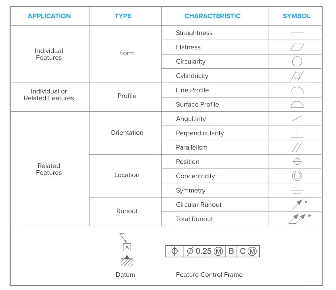
Fig 12:- GD&T symbols
Feature Control Frame (FCF)
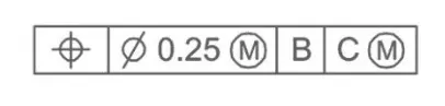
Feature Control Frame
The Feature Control Frame is the notation to add controls to the drawing. The leftmost compartment contains geometric characteristics. In the example above, it is a location control but it can contain any of the control symbols. The first symbol in the second compartment indicates the shape of the tolerance zone. In this example, it is a diameter as opposed to a linear dimension. The number indicates the allowed tolerance.
Next to the tolerance box, there are separate boxes for each datum feature that the control refers to. Here, the location will be measured related to datums B and C. Next to the tolerance or a datum feature is an optional encircled letter, the feature modifier.
The following possibilities can occur:
-
M means that the tolerance applies in the Maximum Material Condition (MMC)
-
L means that the tolerance applies in the Least Material Condition (LMC)
-
U indicates an unequal bilateral tolerance, i.e. for a 1 mm tolerance it may specify it as minus 0.20 and 0.80.
-
P means that the tolerance is measured in a Projected Tolerance Zone at a specified distance from the datum.
-
No symbol installs the tolerance regardless of feature size (RFS)