Week 8 - Challenge 5 - Door Trim Lower
Challenge: Create the Door Trim Plastic component through the given Class-A surface. To begin with, the tooling axis for the given Class-A Surface should be created meeting the requirements of the draft angle and at the end perform the Draft analysis on the model.
Take the Thickness of the component to be 2.5 mm
Aim: To create a Coin Holder Model including creation of Tool Axis, Class B & Class C surfaces and also performing draft analysis on Class A & final output.
Inputs:
1.Class-A Surface
2.Thickness of the component
Class-A Surface
To ensure the connectivity between the surfaces, all surfaces joined using join command.
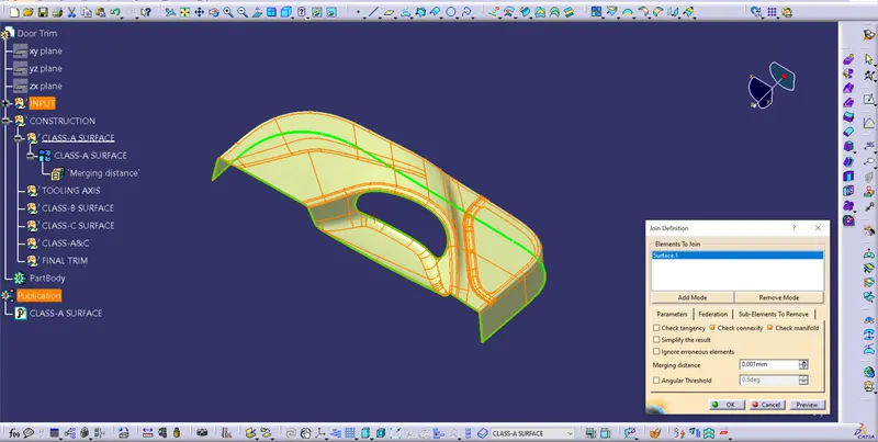
With this it is concluded that all surfaces are joined properly & there are no gaps between the surfaces.
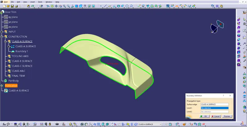
Using boundary command Class-A surface checked for unnecessary open profiles between the surfaces.
Tooling Axis
To create a tooling axis few steps need to be followed
Step 1:
a. Create a point at Centre of Gravity (CG) of the surface
b. Follow the instructions to create a point at CG
Go to Measure tool bar
Measure --> Measure inertia --> Create Geometry --> Non-associative geometry --> Centre of Gravity --> Ok --> OK.
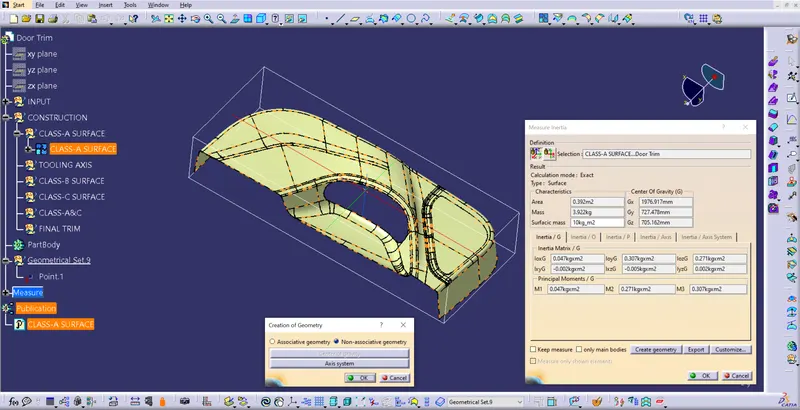
CG point created for the given Class-A surface.
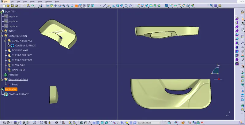
Tooling direction checked for X,Y&Z axis. Tooling can clear all the surfaces in Y-direction.
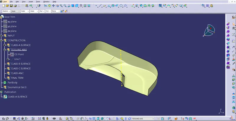
Tooling Axis created along Y-axis using the CG point.
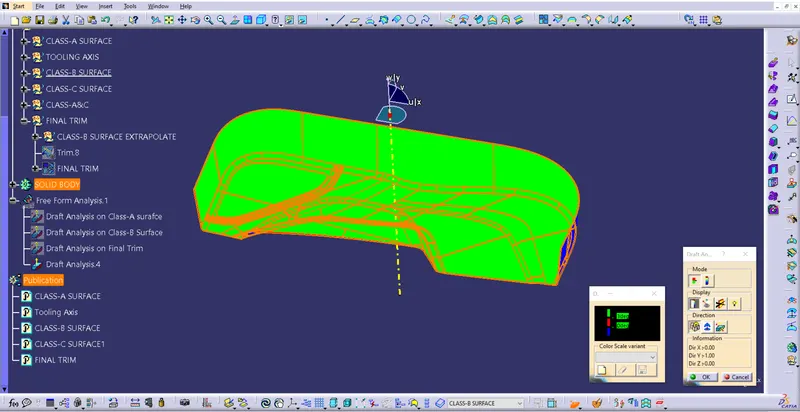
Draft Analysis on Class-A surface
Few steps need to be followed to perform draft analysis.
a. View --> Customise view parameters --> Mesh --> Material --> Ok.
b. The go to Insert --> Analysis --> Feature Draft Analysis
c. Click on compass from the direction, drag & drop compass on the tooling axis in such a way that Z axis to be along the tooling axis.
d. Lock the compass using lock command from direction.
e. Click on the surface to see the results.
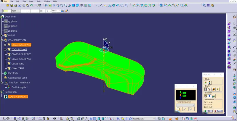
Draft Analysis on Class-A surface.
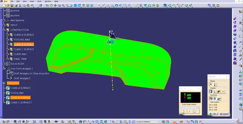
Draft Analysis on Class-B surface.
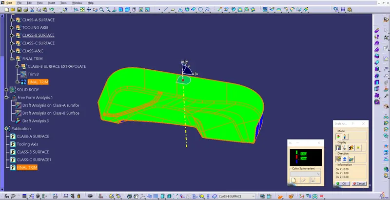
Draft Analysis on Final Trim.
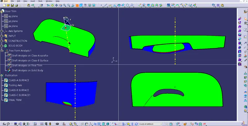
Draft Analysis on Solid Component.
Class-B surface creation
Class-A surface is off-set by thickness.
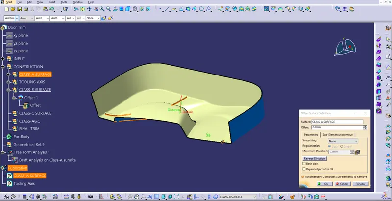
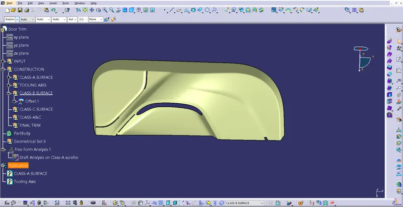
Gaps were created.
A.Work on Area-1
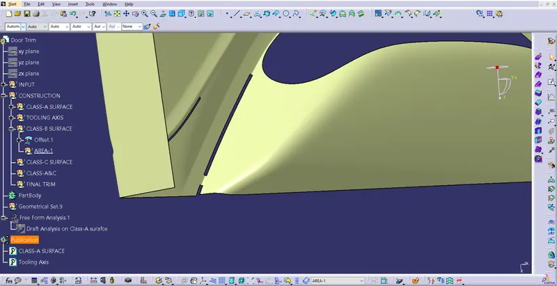
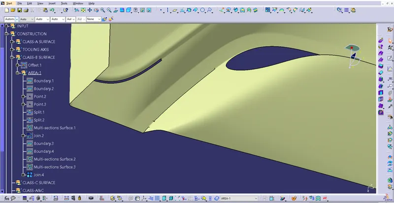
All the gaps at area-1 are filled using the commands like Multi-section surface, boundary & all these patches were joined.
B.Work on Area-2
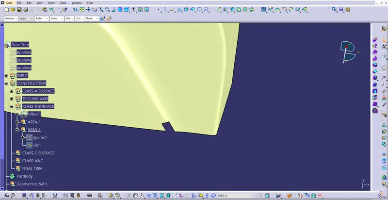
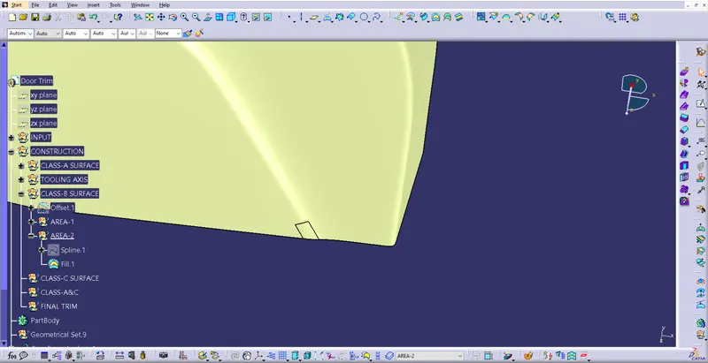
All the gaps at area-2 are filled using the commands like Multi-section surface patches were joined.
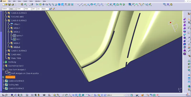
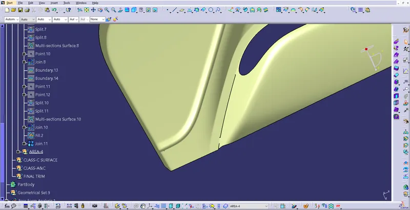
All the gaps at area-3 are filled using the commands like Multi-section surface, boundary & all these patches were joined.
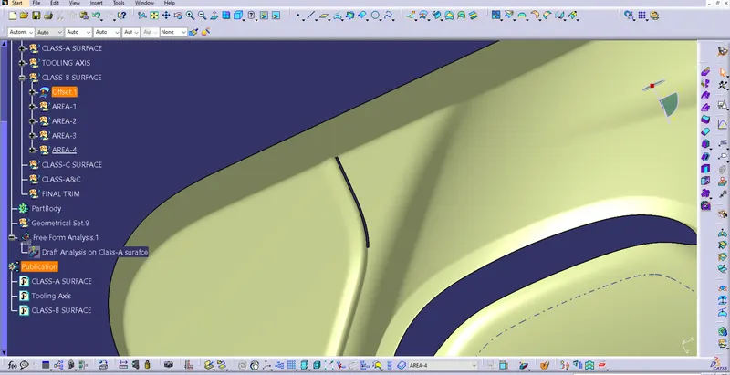
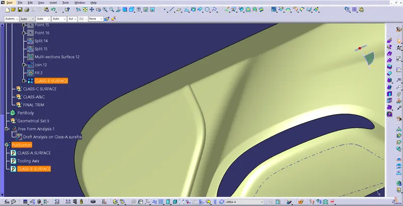
All the gaps at area-4 are filled using the commands like Multi-section surface, boundary, split & all these patches were joined.
Class-C surface Creation
Class-C surfaces created using the boundary of Class-A surface.
Boundaries created & using sweep command drafted in Tooling direction.
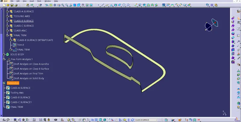
Class-A & C
Class-A & C surfaces are joined together for the final trim of surfaces.
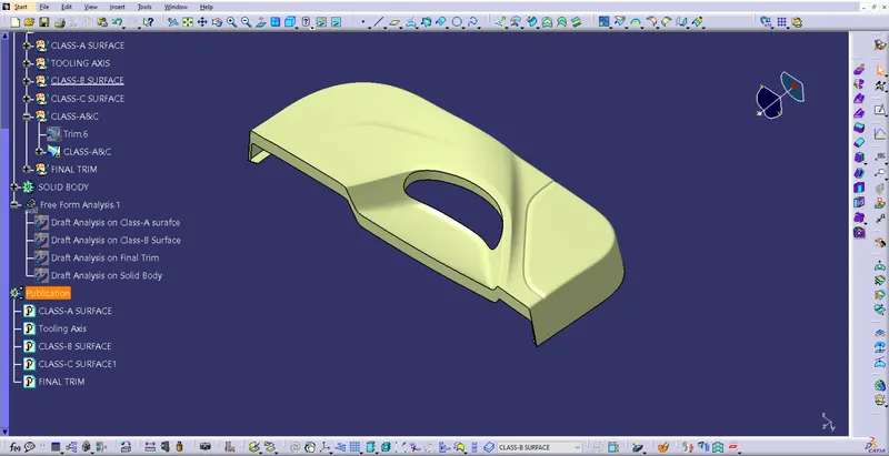
Final trim which included with Class-A, Class-B & Class-C surfaces.
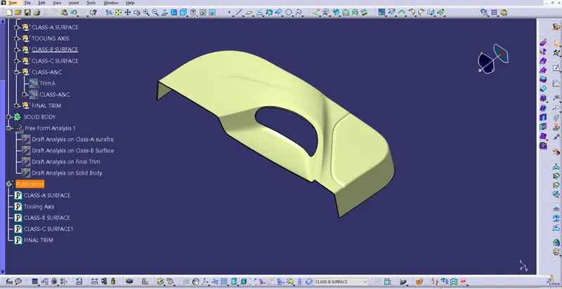
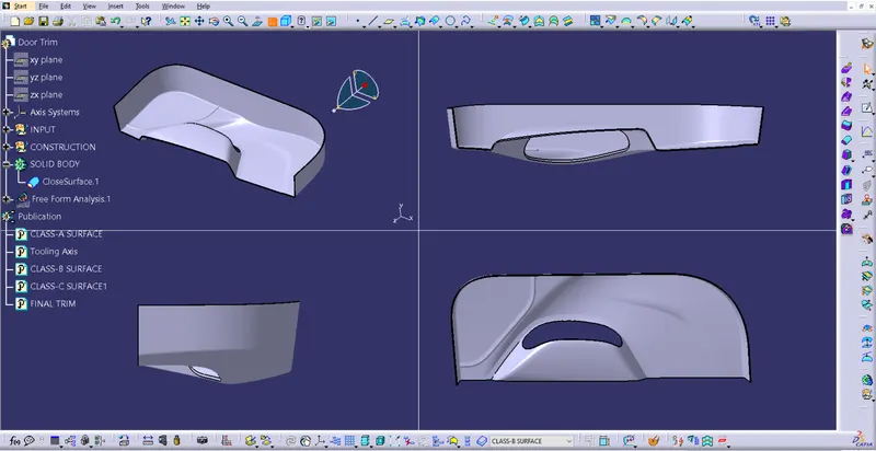
All views of the solid body