Week 8 - Challenge 3 - Coin Holder Design
Coin Holder
Create the Coin Holder Plastic component through the given Class-A surface. To begin with, the tooling axis for the given Class-A Surface should be created meeting the requirements of the draft angle and at the end perform the Draft analysis on the model.
Take the Thickness of the component to be 2.5 mm
Aim: To create a Coin Holder Model including creation of Tool Axis, Class B & Class C surfaces and also performing draft analysis on Class A & final output.
Class A Surface
To ensure the connectivity between the surfaces, all surfaces joined using join.
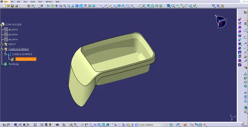
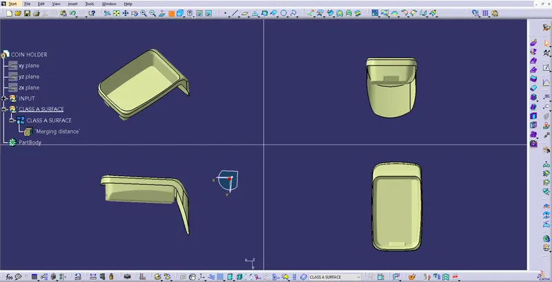
All views of input (Class A) Surface
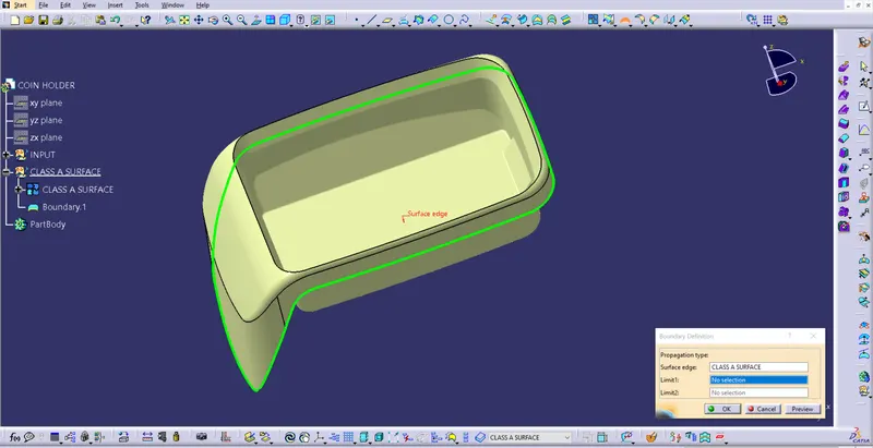
Boundary command also used to ensure there is no open profiles other than holes & cuts in the middle of the surfaces.
Tooling Axis
To create a tooling axis the below method need to be followed
a. Base surface extracted & a point created at the centre of the surface.
b. Axis system created at the point.
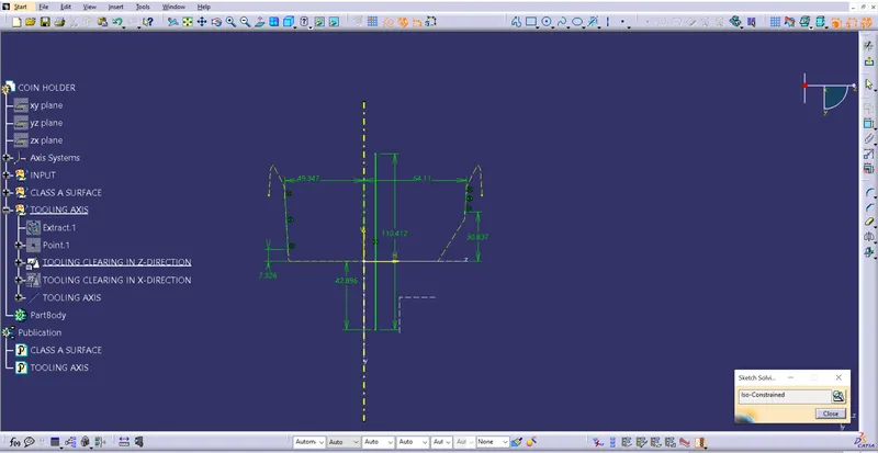
c. Position sketch created and the Class-A surface intersected with YZ plane.
d. Two line created along the incline lines & a bisecting line is created.
e. This is the Tooling Clearing in Z-direction
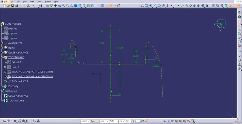
Similarly another bisecting line created in position sketch-2. This is named asThis is the Tooling Clearing in X-direction.
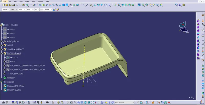
A bisecting line is created at the centre point using the bisecting lines which are created in position sketches 1&2.
This is the Tooling Axis for the model.
Draft Analysis on Class A surface
Few steps need to be followed to perform draft analysis.
Step 1:
a. View --> Customise view parameters --> Mesh --> Material --> Ok.
b. The go to Insert --> Analysis --> Feature Draft Analysis
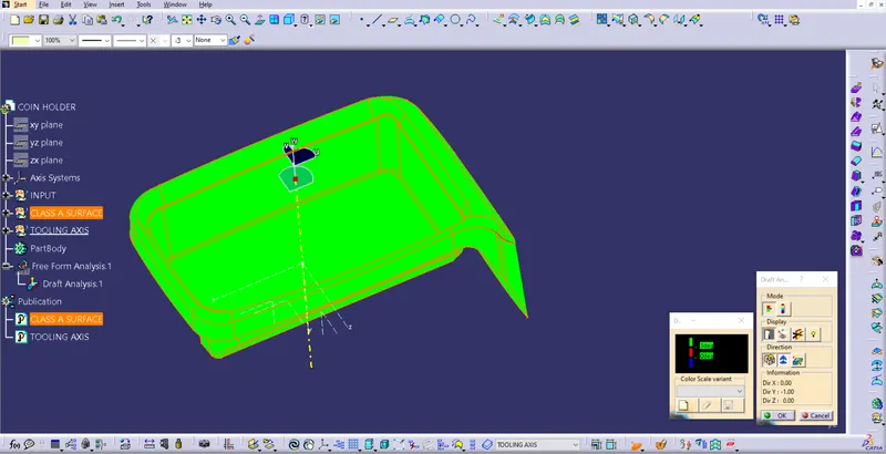
c. Click on compass from the direction, drag & drop compass on the tooling axis in such a way that Z axis to be along the tooling axis.
d. Lock the compass using lock command from direction.
e. Click on the surface to see the results.
Draft Analysis on Final Trim surface
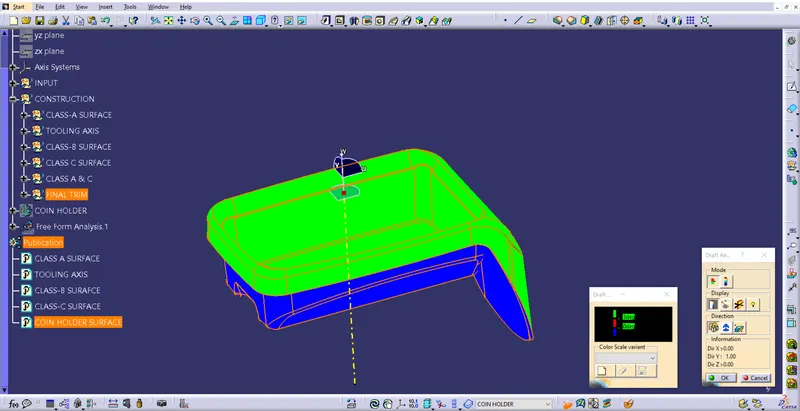
Similar method is used to get the draft analysis results.
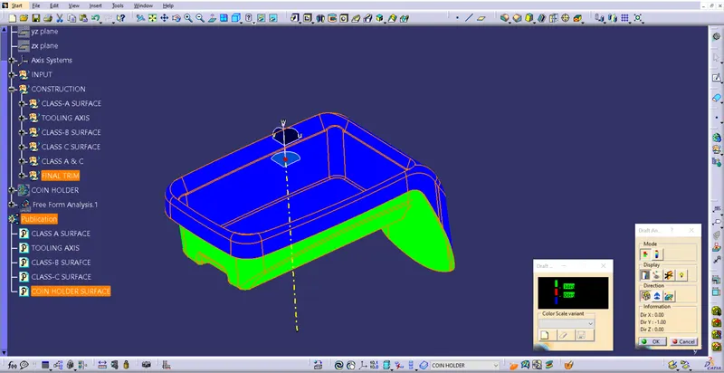
All the faces of the component are haveing required draft angle.
Draft Analysis on closed body of Coin Holder
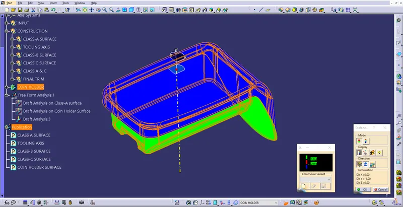
Class-B Surface creation
Given Class-A surface divided in to few parts to simplify Class-B surface creation.
Base
Bottom, Inclined surfaces conisdered as base surfaces.
a. All the surfaces extracted.
b. Untrim performed on all the surfaces.
c. extrapolated the surfaces.
d. Trimmed all surafecs to create a base surface.
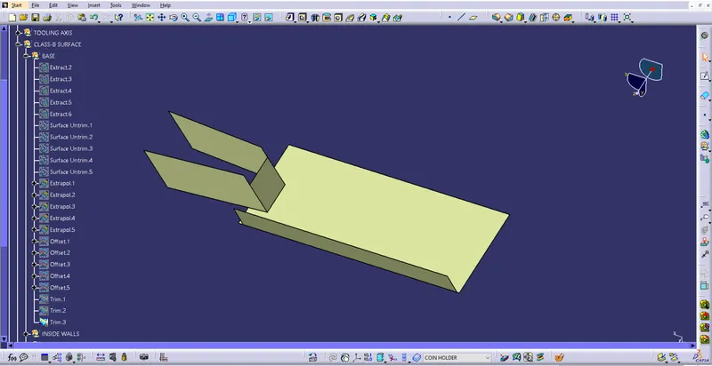
Similarly other surfaces created.
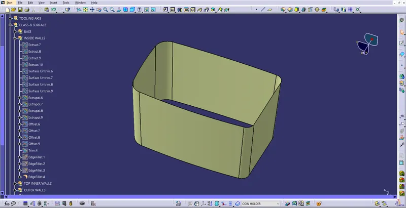
Inside Wall surface
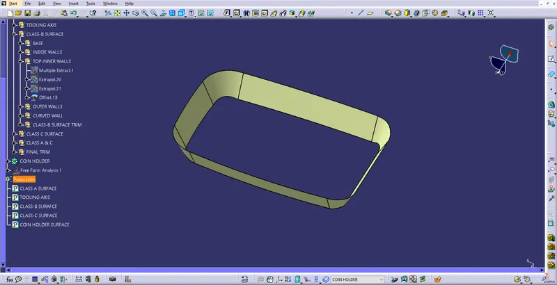
Top wall surface
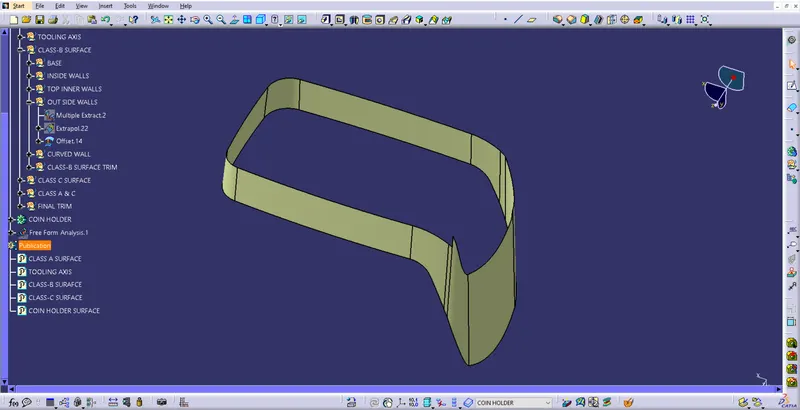
Outer wall
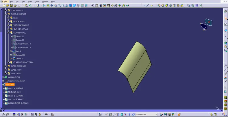
Curved wall
Trimming Class-B Surfaces
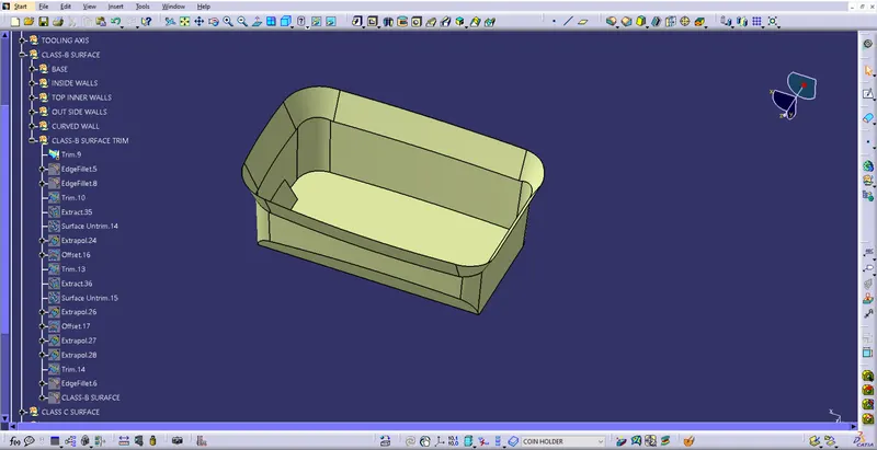
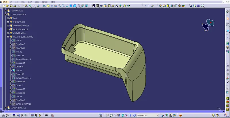
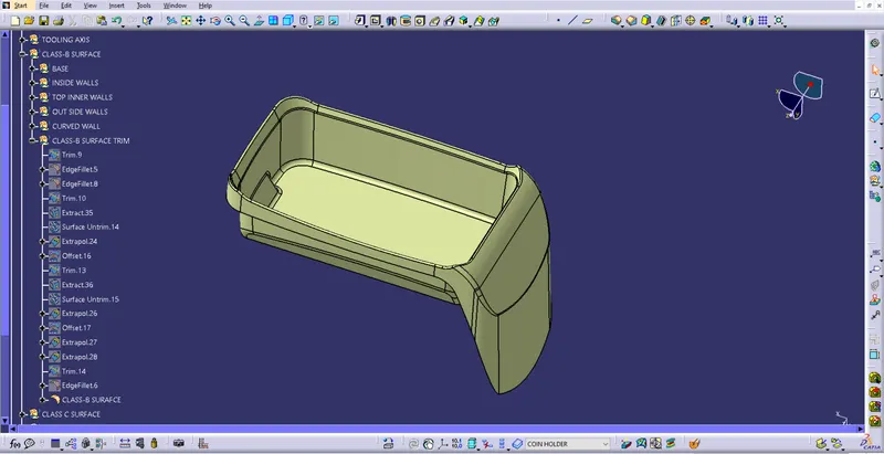
All the surfaces trimmed to get desired shape. Fillet is used to create round the sharp edges & corners.
Class-C Surface creation
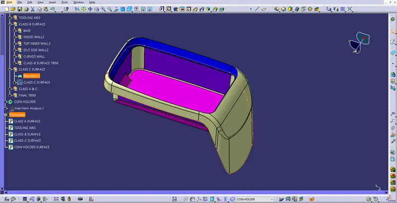
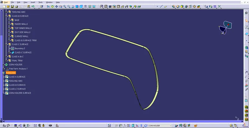
A boundry is created using the Class-A surface.
Using sweep command a surface is created normal to the Class-A surface. This is the Class-C surface.
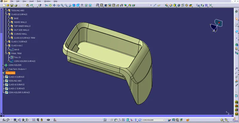
Class-A & C were joined & trimmed with Class-B surface to create final output.
All the surfaces joined to ensure there is no gap between surfaces.
Using clos body command solid body of the Coin Holder created with the final output surface.
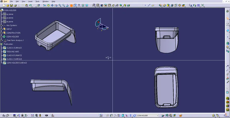
All view of thickened Coin Holder.