Week 8 - Challenge 1 - Base Bracket Design
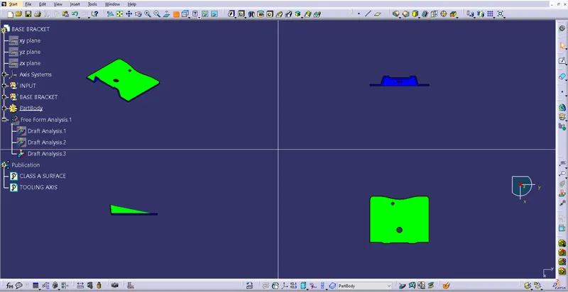
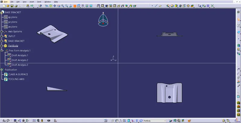
Aim of the challenge: Create the Base Bracket Plastic component through the given Class-A surface. To begin with, the tooling axis for the given Class-A Surface should be created meeting the requirements of the draft angle and at the end perform the Draft analysis on the model.
Thickness of Plastic Part - 2.5 mm
Input
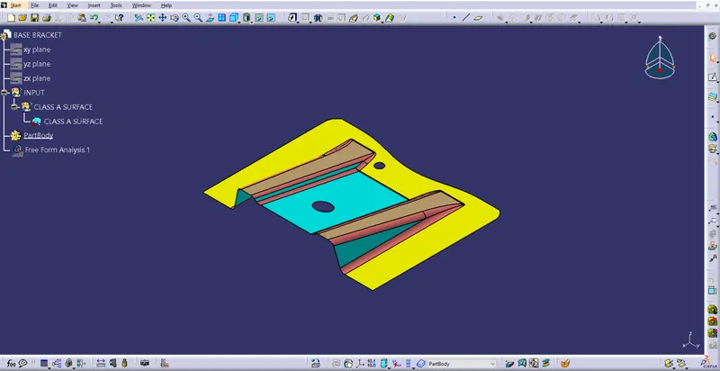
Draft Analysis
Step1: Continuity check.
Use the join command to check the surface continuity, make sure that there is no gap between the surfaces. The given Class-A surface should only have 3 boundaries i.e. 1 outer boundary & 2 holes boundaries, ensure it using boundary command. After using boundary command, visually inspect for the irregular or odd profiles.
Step 2: Creating Tooling Axis: The direction in which the mold moves is called a tooling axis.
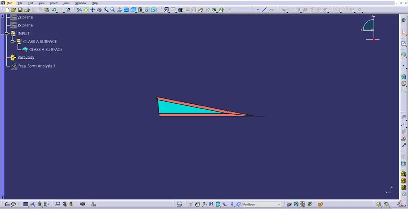
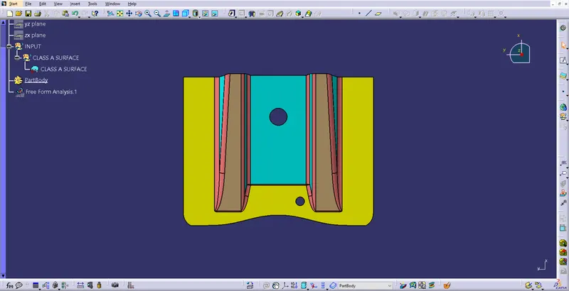
Tooling clearance for the model is inspected in all the X,Y & Z directions.
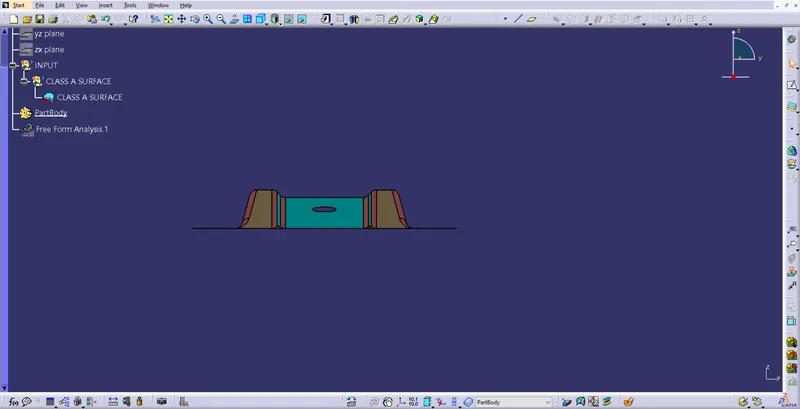
The above image will show the tooling clearing in X-direction, In this direction the model will clear all the faces, but a side core required to obtain the hole, which will increase the mold cost.
In Y-direction, the tooling will not clear the model.
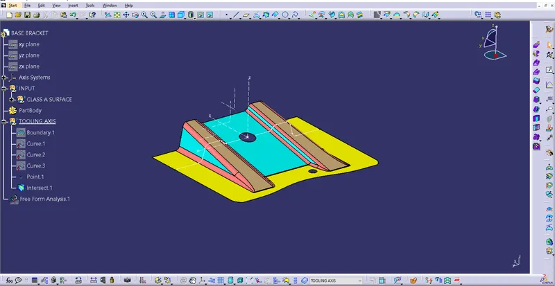
Z-direction is good compared to all the other directions, in this direction tooling will clear all the features of the model.
A point is created at the centre of big hole. An axis system is created at the point. a dummy axis is created along Z-direction.
Using the plane an intersection of the curve is created.
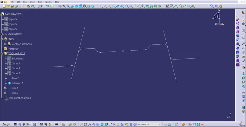
Two lines were created along the sides of inclined surfaces,
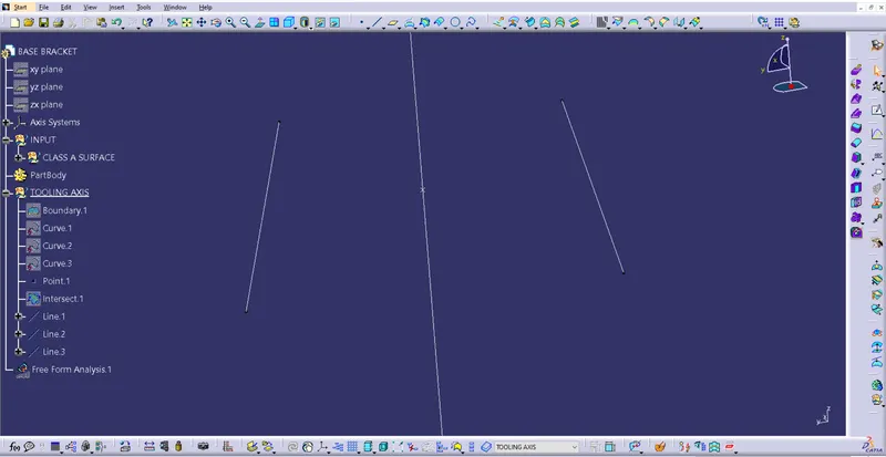
A bisecting line is created using the lines & point created earlier.
The line which equally divides the angle between 2 line is known as a Bisecting line.
Another bisecting line can be created & the bisecting line of the both bisecting lines will be the tooling axis. Here only 1 bisecting line can be created for the given class-A surface, hence it is the bisecting line for the surface.
Step 3: Drafting Analysis
To perform draft analysis, first view parameters need to set. For which the below process has to followed
click on View --> Customise view parameters --> Mesh --> Material --> Ok.
After setting customise view parameters, draft analysis has to be carried out by following procedure
Insert --> Analysis --> Feature Draft Analysis
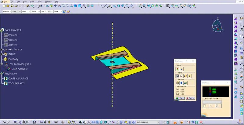
Click on compass symbol from the directing command, drag & drop it on the tooling axis. Ensure that Z-direction should be upward.
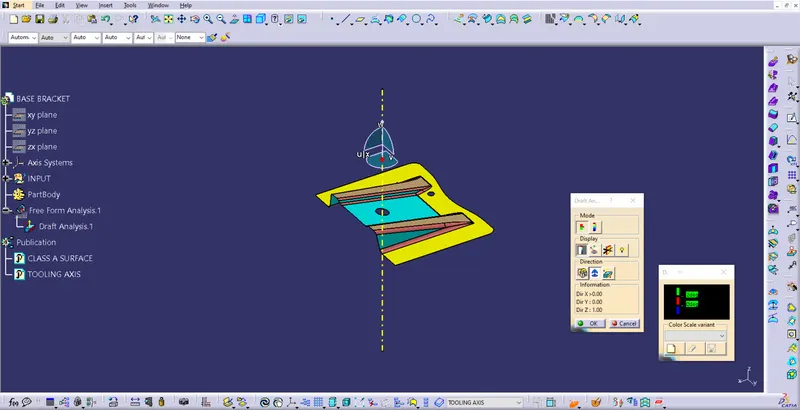
Lock the compass position. using lock command. Click on the surface to see the results.
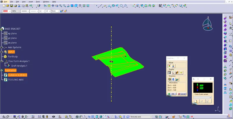
With this it can be concluded that the draft analysis is done & the results were good. All the surface are in green color it means that it has the specific draft angle for all the faces which are inclined to tooling axis.
Class B surface creation:
Step 1: The model divided into 3 parts to create Class-B surface i.e,Rib-, Rib-2, Base surface.
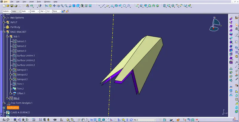
Rib-1 is created by following the below procedure
1. All 3 sides of the rib faces obtained using extract command.
2. The surfaces were untrimmed.
3. Extrapolate all the surfaces
4.Trim the surfaces to get desired shape.
5. Offset the trimmed surface by thickness i.e,2.5mm.
Similarly create all the surfaces.
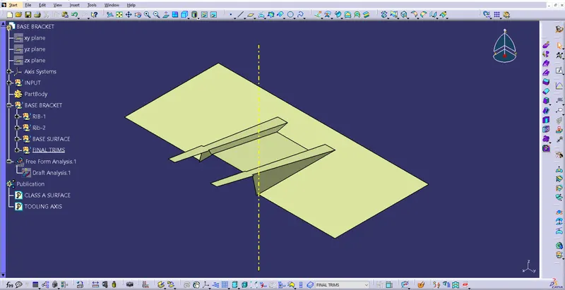
After creating all parts of the Class-A surface, Trim & obtain the desired Class-B surface.
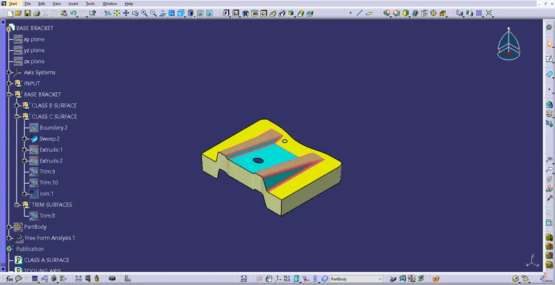
Performed sweep operation along tool axis direction. Hole profiles were extruded in tool axis direction.
Trim command is used to trim & joined the hole extrudes with Class-A surface. Sweep & trims were joined to form Class -C Surface.
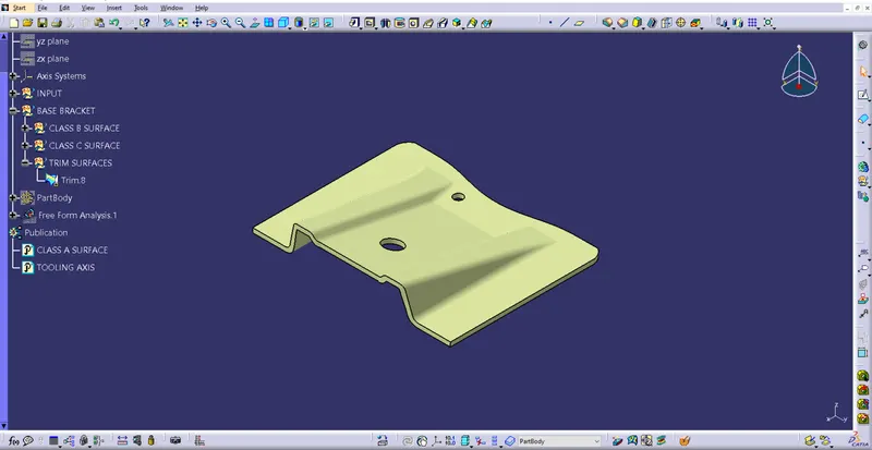
Class B & C surfaces were trimmed to get final output.
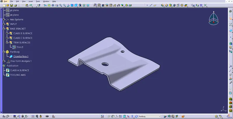
Close body command is used to create the solid model.
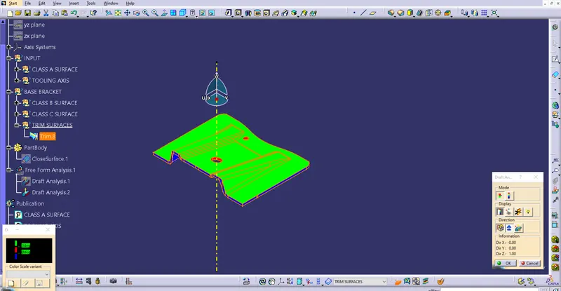
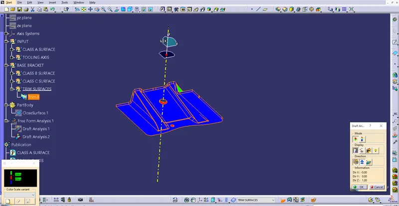
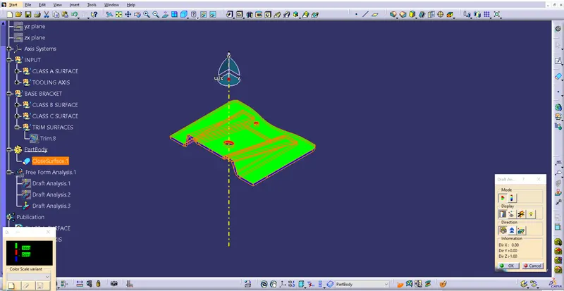
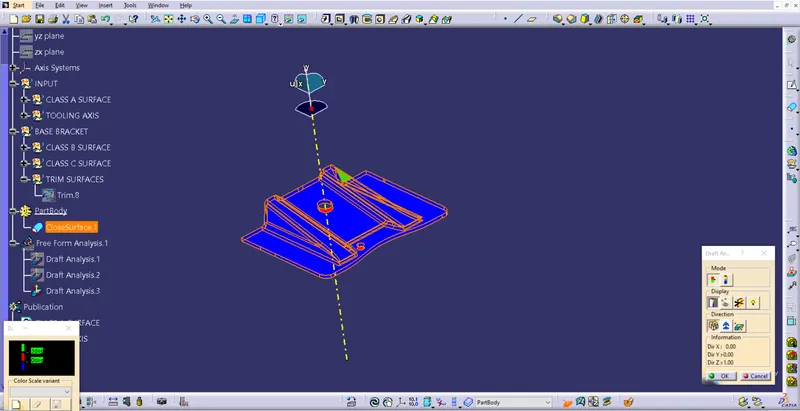
Draft Analysis performed on the final output.