Week 8 - Challenge 2 - Switch Bezel Design
Switch Bezel
Create the Switch Bezel Plastic component through the given Class-A surface. To begin with, the tooling axis for the given Class-A Surface should be created meeting the requirements of the draft angle and at the end perform the Draft analysis on the model.
Take the Thickness of the component to be 2.5 mm
Aim: To create Switch Bezel including creation of Tooling Axis, Class B & C surfaces & draft analysis on both Class A & final output.
Input:
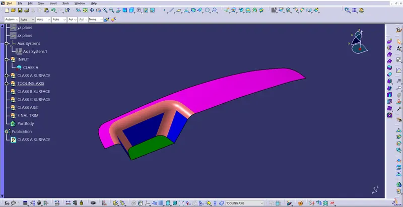
To ensure the connectivity between the surfaces join command is used.
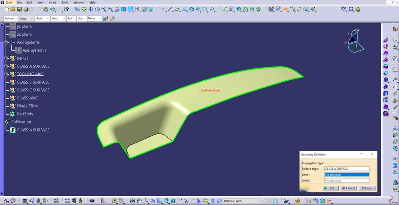
Later boundary command also used to ensure there is no open profile in the middle of the surfaces.
Tooling Axis:
Step 1:
a. Extracted base surface & a point is created at centre of the surface.
b. An axis system is created at the point.
Step 2:
a. Position sketch is made, in which given Class-A surface is intersected with YZ plane, and two lines were created along the incline profile.
b. A bisecting line is created using both the lines created in sketch-1.
c. There no 2nd side surface is available to create intersection between class-A & XZ plane. So another position sketch is created in which a line is created with some approximate angle.
Step 3: A bisecting line created using bisecting line 1 and line created in sketch-2.
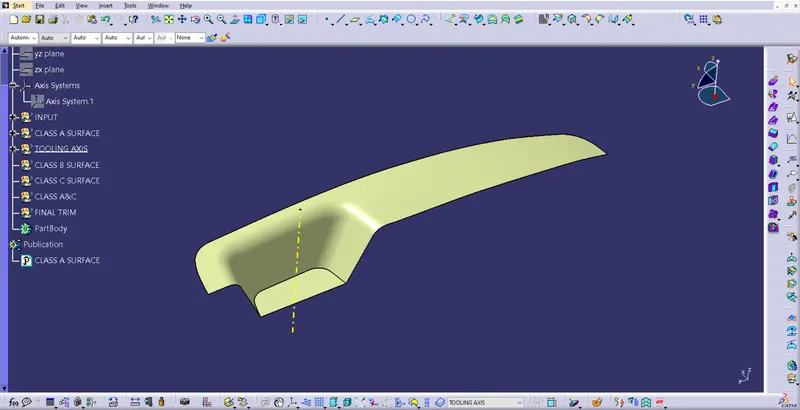
This is the tooling axis for the part.
Draft analysis on Class-A surface
Few steps need to be followed to perform draft analysis.
Step 1: Go to View tab
View --> Customise view parameters --> Mesh --> Material --> Ok.
Step 2:
a.Go to Insert --> Analysis --> Feature Draft Analysis
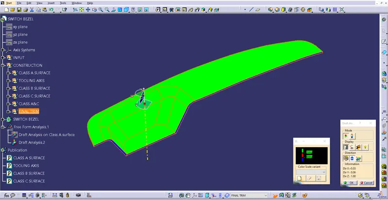
b. Click on compass symbol, drag & drop compass on tooling axis. Ensure the position as shown in below image
c. Click on lock symbol, and click on the surface to see the results.
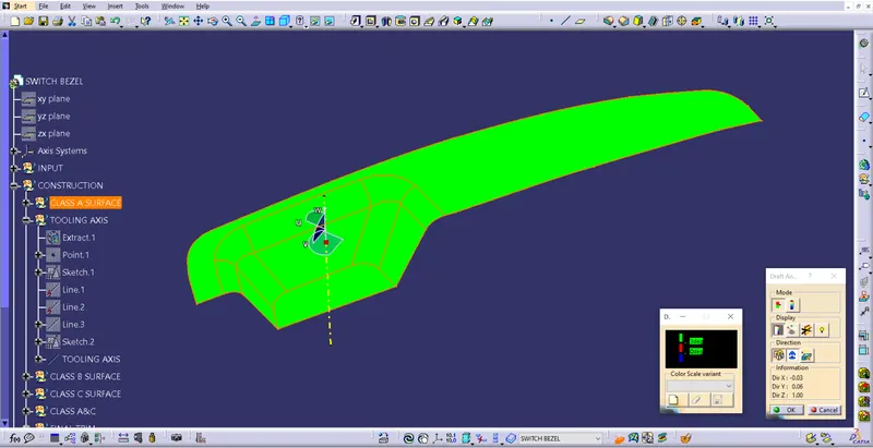
Draft analysis on Final Trim surface
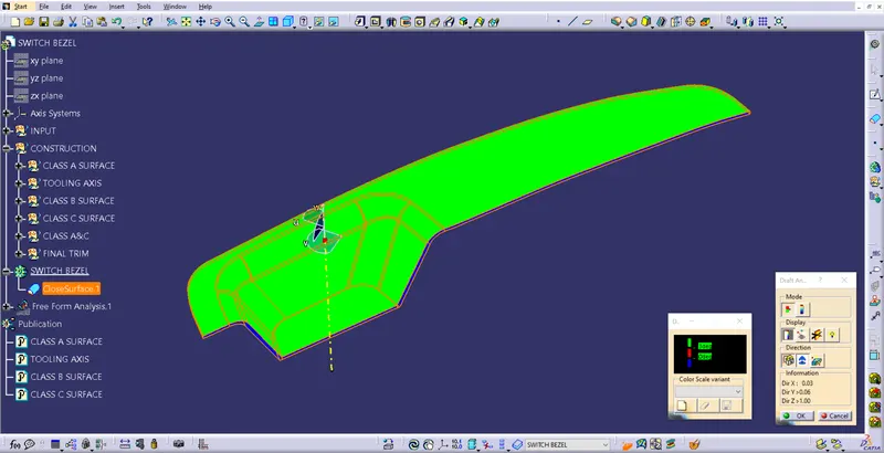
Draft analysis on solid body
Class-B surface Creation
Bezel Surface
Following procedure helps to create Bezel surface
a. Extract the Bazel surface.
b. Untrim the surface.
c. Off-set surface by thickness i.e. 2.5mm.
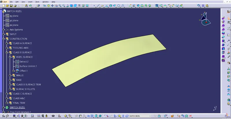
Bezel Surface
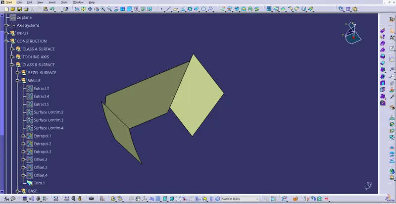
Following procedure helps to create Bezel surface
a. Extract the wall surfaces.
b. Untrim the surface.
c. Extrapolate the surfaces.
d. Off-set surface by thickness i.e. 2.5mm.
e. Trim them to gect required shape.
Base Surface
Following procedure helps to create Bezel surface
a. Extract the base surfaces.
b. Untrim the surface.
c. Extrapolate the surfaces.
d. Off-set surface by thickness i.e. 2.5mm.
Perform a final trim on Bezel, wall & base surfaces. Perform fillet to get desired Class B surface.
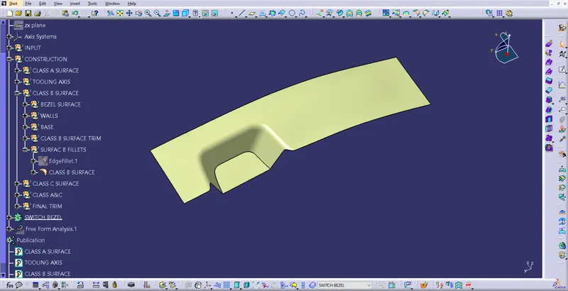
Class-C surface Creation
Using a boundary command, out-line of the surface created. The profile divided into 4 pieces & sweep surfaces created using sweep with draft direction, the direction is along tooling axis.
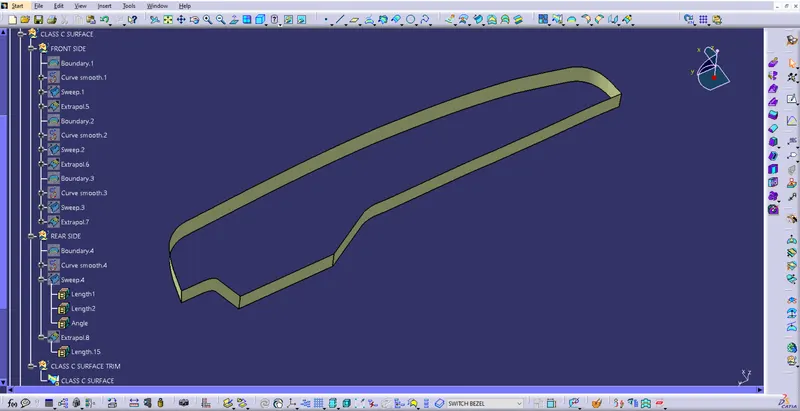
All the surfaces extrapolated & trimmed to get desired shape.
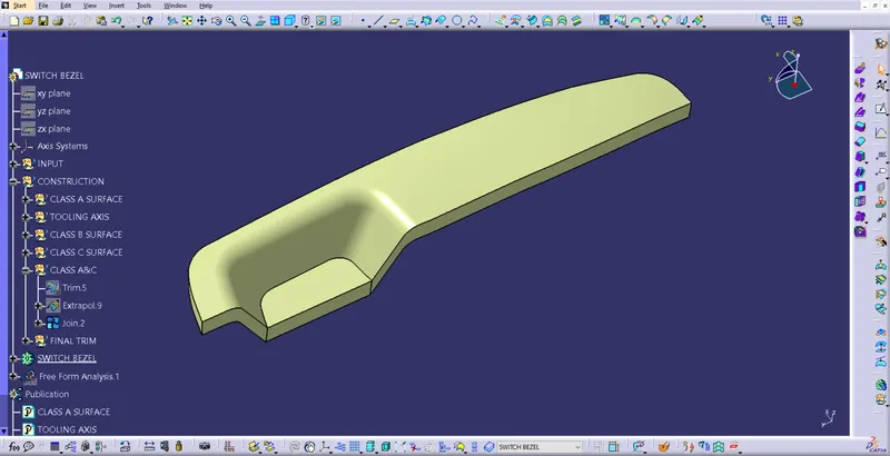
Join Class A & C, ensure the is no discontinuity or gaps between the surfaces.
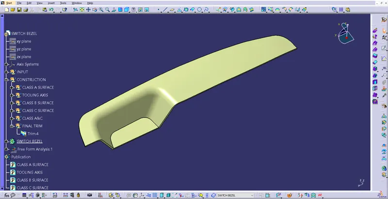
Trimmed Class A&C with Class be surface to get final output.
The Model is checked for continuity & made solid using close command.
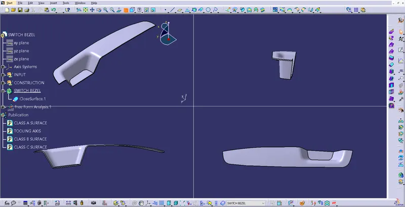
Isometric, Front, Side & Tops views.