Week 9:- 2D Detailing Challenge
#1_Drawing Templates: A drawing template enables you to create exact circles, squares, lines, arcs, and more without reaching for a compass, ruler, or protractor. It's a necessary tool for executing clean-lined blueprints, sketches that demand precision, or crisp compositions for bullet journals.
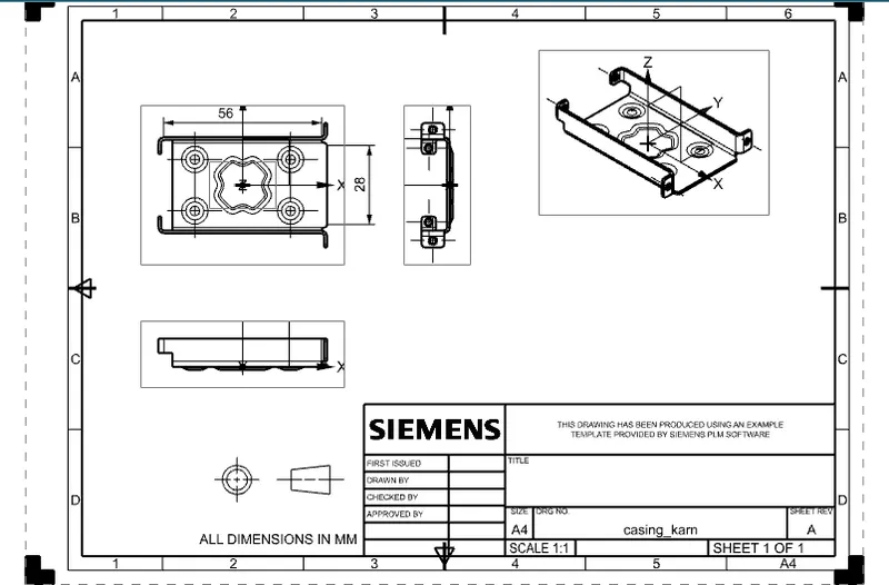
Drawing Templates are the files of frames and title block whic convey information which are used to produce 2 D Sketches from 3D Models. Information Like Project Name, Company Name, Developer's Name, Sheet Number, Sheet Size, Scale, etc.
#2_Angle of Projection: The angle at which an observer draw an object to convert it from 3D to 2D plane such as real object image to a plane paper is known as angle of projection.
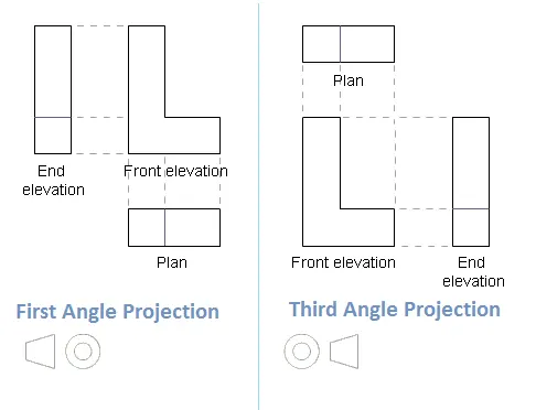
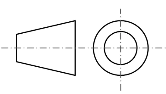
#3_First Angle Projection :
In the first angle projection, the object is placed in the 1st quadrant. The object is positioned at the front of a vertical plane and top of the horizontal plane. First angle projection is widely used in India and European countries. The object is placed between the observer and projection planes. The plane of projection is taken solid in 1st angle projection.
Third Angle Projection :
In the third angle projection, the object is placed in the third quadrant. The object is placed behind the vertical planes and bottom of the horizontal plane. Third angle projection is widely used in the United States. The projection planes come between the object and observer. The plane of projection is taken as transparent in 3rd angle projection.
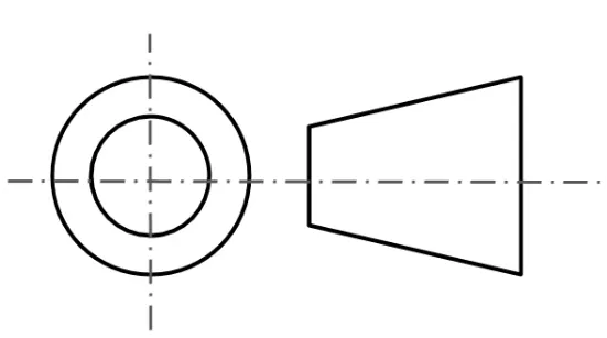
In practice only first angle quadrant and the third angle quadrant are used since these are pure views. The second angle quadrant and fourth angle quadrant are combination of first and third angle projections and cause confusion to the reader.
#4_Geometric Dimensioning & Tolerancing:
GD&T is an acronym that stands for Geometric Dimensioning and Tolerancing. It is a symbolic language used by designers to communicate manufacturing constraints and tolerances clearly. This information is conveyed in the form of annotations included in the design of the part.
To start, the designer encodes the information into the model, using GD&T’s specific grammar and syntax rules. This eliminates the lengthy notes in a drawing that used to be used to describe the form. With GD&T we have a broad range of tolerances, giving the designer a certain flexibility to communicate dimensional constraints based on the requirements of the part.
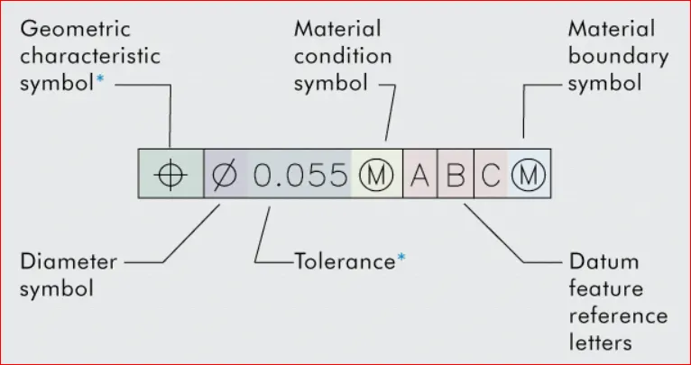
#Benefits: Geometric Dimensioning and Tolerancing is a way of encoding tolerances in a clear and concise manner. Done properly, it can improve the quality of your manufacturing process as well as
- Removes ambiguity by applying universally accepted symbols and syntax.
- Uses datums and datum systems to define dimensional requirements with respect to part interfaces.
- Specifies dimensions and related tolerances based on functional relationships.
- Expresses dimensional tolerance requirements using methods that decrease tolerance accumulation.
- Provides information that can be used to control tooling and assembly interfaces.
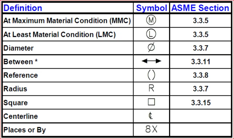
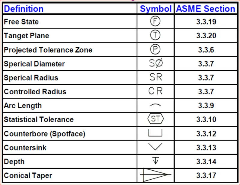
#5_GD&T Symbols: