Week 9:- 2D Detailing Challenge
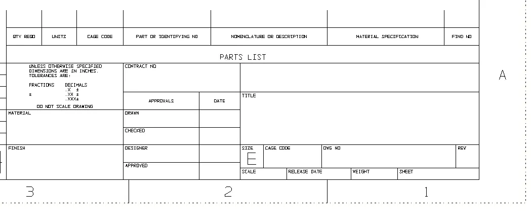
1. What are drawing templates?
Compared to conveying data in verbal or written form, symbols and drawing provide information in a better and more understandable way minimizing errors caused by miscommunications or misunderstandings.
- Drawing templates are standards decided by the client.
- Drawing templates are used to define all the parts or various parameters in a fixture in a systematic manner.
- Drawing templates are usually of .dwg extension and has blank page with frame for filing of details with set styles, setting for title blocks.
- There are various details present on the template which can be edited as per the requirements and space for adding required note for manufacturing process or details like finishing, tolerances, name of parts, name of assembly, etc.
- Drawing templates are usually created at the start of the project as it can be used as base for all the detailing files that follow.
- Drawing templates can be different for different sheet sizes.
Need for templates:
They are needed to set the view display, place notes if any for the manufacturing process, place symbols wherever necessary for easy understanding or 2D Drawing.
Define tables and show dimensions of the setup. The templates for machined parts, cast parts and the likes are different.
Templates are made for the purpose, that part of the detailing process is already done at the start of detailing. Hence, templates should be created such that it reduced the work during the detailing process.
Templates should contain the following information in addition to other info particular to the project.
- Company name
- Project name
- Sheet size
- Quantity
- Scale
- Date
- Unit of measurement
- Revision date
- Drawn by
- Angle of projection
- Sheet number
2. What do you understand by angle of projection?
Angle at which the observer looks at an object and draws it in 2D from 3D from real object to paper is called as angle of projection.
Parallel projection is used to generate drawing which is used for manufacturing of the part. Angle of projection is usually perpendicular to the object. A plane is an imaginary surface on which pictures are drawn. Usually a minimum 3 views of the object is required to be able to present all the dimensions required for manufacturing.
When two planes one horizontal and one vertical are considered as principal planes. These planes are placed such that they form 4 quadrants. When the object is placed in 1 quadrant it is called first angle projection, i.e., the plane is behind the object. When object is place in the 3rd quadrant, it is called 3rd angle projection, i.e., object is behind the plane.
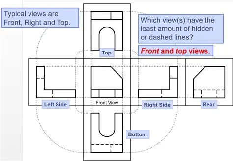
In orthographic projection there are following views:
- Front view
- Top view
- Back view
- Bottom view
- Right side view
- Left side view
Orthographic drawing:
- The front view and top view always form over/under each other.
- The top view shows the length and breadth of the object.
- The side view shows the length and height of the object.
- The front view shows the length and height of an object.
- The side view is always beside the front view.
- The hidden detail of an object is shown as a dotted line.
Selecting the view:
- Most detailed view should be selected.
- The selection of views with maximum detail should be made.
- The selection of views with more internal details should be made.
- The selection of view of required details should be made.
3. What is first angle and third angle projection? Why can't we use the second and fourth angle of projection?
First Angle of Projection:
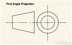
The object is placed in the first quadrant. The object is positioned at the front of a vertical plane and top of the horizontal plane. First angle projection is widely used in India and European countries. The projection plane is behind the object.
- The object is in the first quadrant.
- The plane of projection is assumed to be non transparent.
- Top view comes below the front view.
- Right side view is on the left.
Third Angle of Projection:
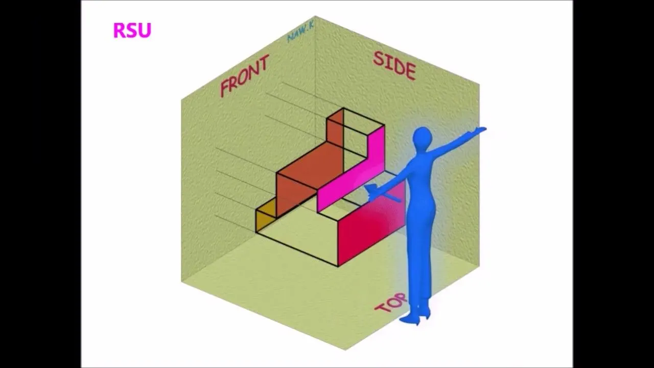
The object is placed in the third quadrant. The object is positioned behind the vertical planes and at the bottom of the horizontal plane. Third angle projection is widely used in the United States. The projection plane is placed in front of the object.
- The object is in the third quadrant.
- The plane of projection is assumed to be transparent.
- Top view is above the front view.
- Right side view is on the right side.
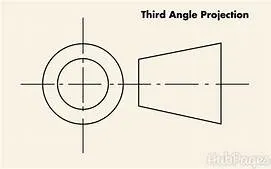
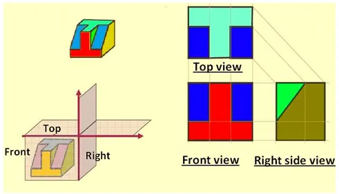
2nd and 4th angle projection has limitations and hence aren't used. When the object is projected, the projection planes and after rotation, the views overlap. Overlapping projection creates confusion and hence is not used.
4. What is What is GD&T? What are the benefits of GD&T?
Geometric Dimensioning and Tolerancing (GD&T) is a system for defining and communicating engineering toleracnes and relationships. It uses symbols on drawings and computer-generated three-dimensional solid models that explicitly describe nominal geometry and its allowable variation. It tells the manufacturing staff and machines what degree of accuracy is needed on each controlled feature of the part. GD&T is used to define the nominal (theoretically perfect) geometry of parts and assemblies, to define the allowable variation in form and possible size of individual features, and to define the allowable variation between features.
- Dimensioning specifications define the nominal, as-modeled or as-intended geometry. One example is a basic dimension.
- Tolerancing specifications define the allowable variation for the form and possibly the size of individual features, and the allowable variation in orientation and location between features. Two examples are linear dimenions and feature control frames using a datum ref.
Advantages of using GDnT:
- Saving Money: GD&T enhances design accuracy by allowing for appropriate tolerances that maximize production. For many projects, the process provides extra or bonus tolerances, further increasing cost effectiveness.
- Ensuring Dimensional and Tolerance Requirements: By explicitly stating all design requirements, a thorough GD&T process guarantees accurate fulfillment of all dimensional and tolerance specifications.
- Assisting Digital Design Methods: Clear, concise GD&T data is readily adaptable to digital design programs, including nearly universally used 2D and 3D CAD files.
- Offering Uniformity and Convenience: As a single, consistent language, GD&T reduces guesswork and interpretation while ensuring consistent geometries across design and manufacturing.
- Providing Accurate Communication: Today’s intricate designs demand the most accurate and reliable communication. GD&T enables designers, manufacturers, and inspectors to communicate clearly with one other, saving time and making the process more efficient.
5. Explain all the symbols used in GD&T?
|
Sr. No. |
Symbol |
Name |
Type of Control |
Description |
|
1 |
 |
Straightness |
Form |
Controls the waviness of a feature in one particular translational axis. Gauge is run along straight parallel lines to check the straightness. |
|
2 |
 |
Flatness |
Form |
Controls the irregularity of the surface by restricting the ups and downs of the surface in between to imaginary planes. The gauges are moved in a zig-zag pattern to check the flatness all over the surface. |
|
3 |
 |
Circularity |
Form |
Controls the size of the feature only in circular direction over the feature. The gauge is moved only around the feature to check the circularity of the hole/pin. |
|
4 |
|
Cylindricity |
Form |
Controls the size of the feature in circular direction as well as along it’s depth. The gauge follows a helix path to check the cylindricity of a feature. |
|
5 |
|
Profile of a Line |
Profile |
It controls the profile at one given line by providing two parallel lines around the feature and giving it a value, which is the tolerance. |
|
6 |
|
Profile of a Surface |
Profile |
It controls the profile of any surface by providing two parallel planes around the feature which is separated by a tolerance value. |
|
7 |
|
Perpendicularity |
Orientation |
Controls the orientation of the feature by giving tolerance of some angle with respect to the datum reference. |
|
8 |
|
Angularity |
Orientation |
Allows some tolerance limit to change in the angle with respect to reference datum. |
|
9 |
|
Parallelism |
Orientation |
Allows the feature some tolerance of being at an angle to the datum it should be parallel to. |
|
10 |
|
Circular Runout |
Runout |
It controls the circular area around the datum axis. |
|
11 |
|
Total Runout |
Runout |
It controls the surface of the runout around the datum axis. |
|
12 |
|
Position |
Location |
Controls the position of the feature with respect to reference datums i.e., allows some tolerance to the positioning of the feature. |
|
13 |
|
Concentricity |
Location |
Same as position tolerance, controls concentricity of revolution of the feature with respect to central datum. |
|
14 |
|
Symmetry |
Location |
Controls the symmetry of two surfaces, about a central axis. |


