Week -2
Aim:
- Create a doorbell model using solenoid in Simulink.
- Build a model using thermister to sense the temperature.
1. Doorbell Model:
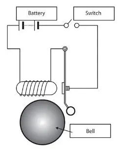
Here, Doorbell consists of the main parts which include a solenoid, battery as a source, switch & bell. Here, the important part is the Solenoid on which the working of the plunger i.e movement depends. A solenoid is just an electromagnet where the coiled wire surrounds a metal piston. The piston contains magnetically conductive metal, so it can be moved backward or forward by the electromagnetic field. A magnetic field is produced here with the help of battery source.
Simulink Model:
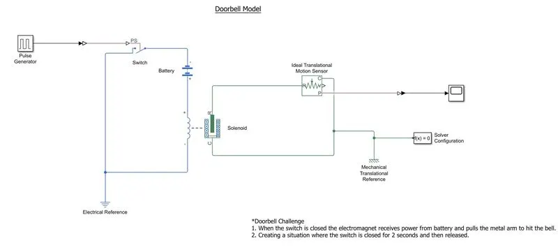
Working:
- Here we use a pulse generator for the input condition given in the question.
- To pass the input signal from the Simulink block to the simscape block through the switch, a Simulink to PS converter block is used.
- The input signal is provided to a switch. A battery is connected to a solenoid to generate the magnetic field for movement of the plunger and the switch with electrical reference as a ground.
- To track the position of the plunger, a Translational motion sensor is used. The output of the solenoid block from connector R is given to the motion sensor as an input which will ultimately give an output of position that can be observed in the graph through the scope block.
- Translational Reference block is used for fixed point and also solver configuration is provided to solve the model with simscape block.
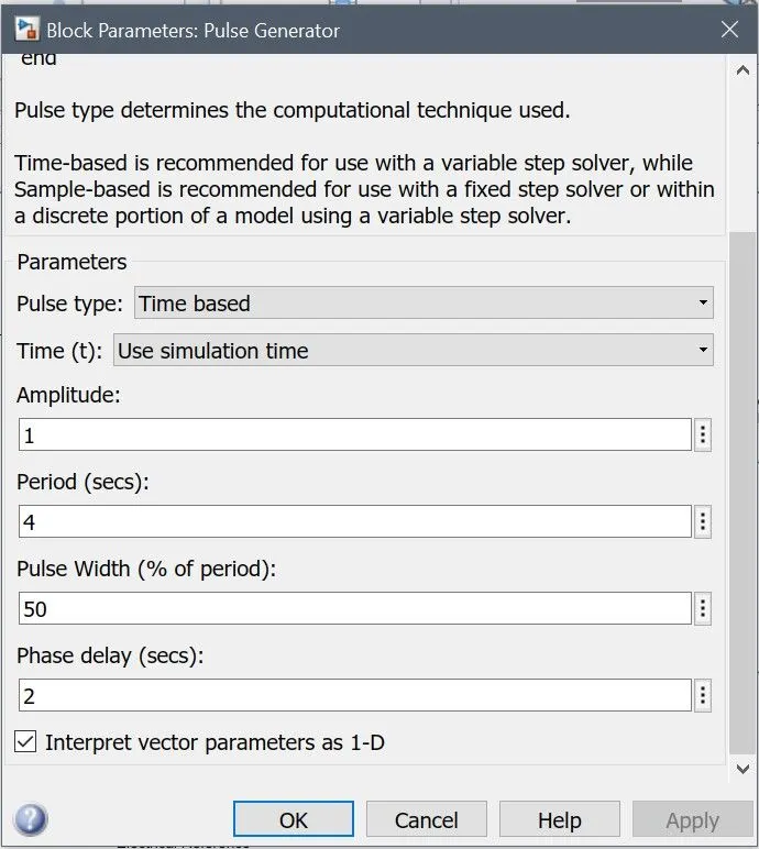
Inputs:
*Here we creating input through pulse generator. Remaining blocks are remained to default.
Output:
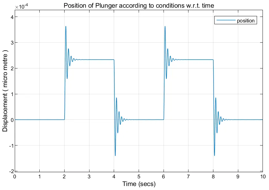
According to the above example of the output, we can change the various input parameters to get the output with smooth intensity signal. For Ex: we can change the spring constant , plunger mass, etc according to the conditions for the desired output.
Result:
Here we run the model for 10 sec as it is a stop time provided here. The graph is obtained for 10 seconds. From the graph, it can be seen that due to the delay of 2 sec at the initial stage, the position of the plunger is at 0. But after that, for the next 2 seconds, the solenoid will engage and there will be movement of the plunger. Again for the next 2 sec, the position will come to 0 and for the next 2 seconds plunger will show displacement. This process continues for a total of 10 seconds according to the stop time provided.
2. Thermister Model:
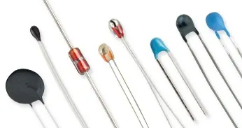
Fig: Thermister
A thermistor is a resistance thermometer or a resistor whose resistance is dependent on temperature. The term is a combination of “thermal” and “resistor”.
There are two types of thermistors: Negative Temperature Coefficient (NTC) and Positive Temperature Coefficient (PTC). With an NTC thermistor, when the temperature increases, resistance decreases. Conversely, when the temperature decreases, resistance increases. This type of thermistor is used the most.
A PTC thermistor works a little differently. When temperature increases, the resistance increases, and when temperature decreases, resistance decreases. This type of thermistor is generally used as a fuse.
Aim: To Model a control system using a thermostat for a Dc motor fan.
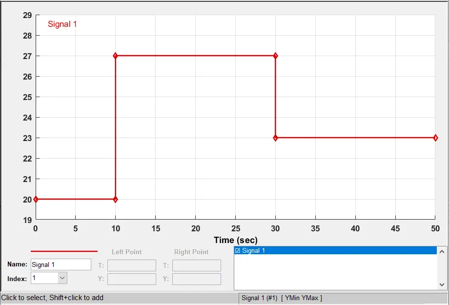
Conditions: Temperature source must be kept at 0 to 20 degrees for 10 sec. 27 degrees for next 20 sec. And 23-degree celsius for next 20 sec. The total cycle is of 50 sec.
The threshold value for the thermostat should be 25 degrees Celcius.
Simulink Model:
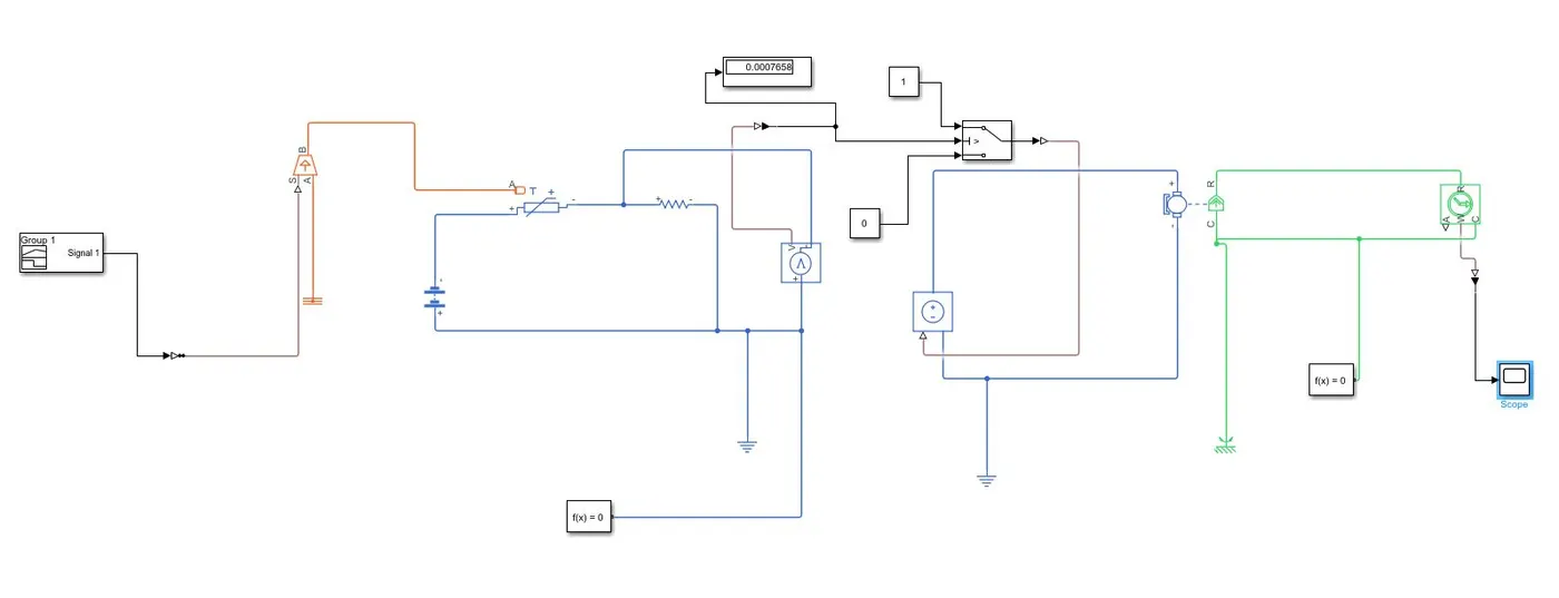
Working:
- The sensor is connected with a variable heat source.
- A battery source is provided to the heat sensor.
- a voltage sensor is connected to the thermostat circuit for measuring the change in voltage.
- the output of the voltage sensor is connected with a switch as a reference.
- the switch is connected with the current source for DC motor.
- the output for the DC motor is connected with the ideal rotation motion sensor. which is connected with a scope block.
Input:
Output:
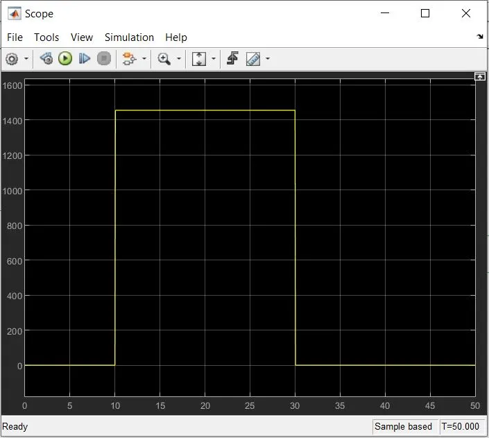
Conclusion: We were able to switch on the fan at a particular temperature.