Week - 4
*Answering the following conditions:
- Implement control logic of a “washing machine” using Stateflow as per given sequence:
Conditions:
- If the power supply is available, the system gets activated.
- If the water supply is not available, stop the process & indicate through LED.
- Soaking time should be 200s followed by Washing time of 100s.
- Then rinsing happens for next 20s & dryer runs for 50s.
Ans:
Control Logic and State Flow:
- State flow refers to simulink.
- Control logic is implemented in simulink environment using stateflow diagrams.
- State flow can be said as the step-by-step process that flows from one state to another with a given time delays or conditions.
Control Logic:
Control logic is a key part of a software program that controls the operations of the program. The control logic responds to commands from the user, and it also acts on its own to perform automated tasks that have been structured into the program.
- Control logic can be modeled using a state diagram.
- It works accordingly due to the time delay or the conditions given between the states.
*Here we are controlling a washing machine with pre-built settings.
Regular steps inside a washing machine:
- Power supply
- Clothes
- Filling water
- Soaking
- Washing
- Rinsing
- Drying
Procedure inside the chart (operation):
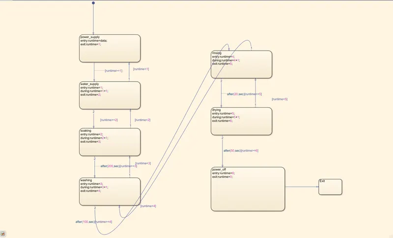
- Here the state blocks are used to run the process according to the flow described by the user.
- Here we are defining every state box value as 'runtime' where the state boxes are identified by their 'runtime values'.
- We are taking input to our start location, and after that we are adding a number in every state and assigning the each and every state with their respective state 'runtime numbers'.
- In our flow, every state gets activated by their 'runtime number' and the flow is controlled by the conditions which we are giving between them.
- Every stateflow is controlled by the conditions between them.
- Outputs are displayed using 'LED lamps'. One for Power ON/OFF, another for Water ON/OFF and another for Washing.
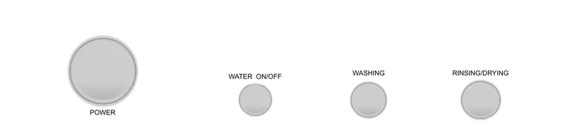
*Green light is for ON, yellow light is for water ON & Red is for Power OFF.
State Flow (i.e during runtime's):
- Power supply (runtime = 1)
- Water supply (runtime = 2)
- Soaking (runtime = 3)
- After 200sec-Washing (runtime = 4)
- After 100sec-Rinsing (runtime = 5)
- After 20sec-Drying (runtime = 6)
- After 50sec-Power off (runtime = 0)
Input:
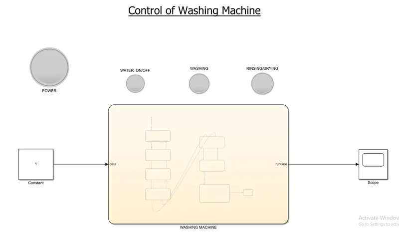
*It is given by a constant block.
Operation:
*It is done by stateflow.
Output:
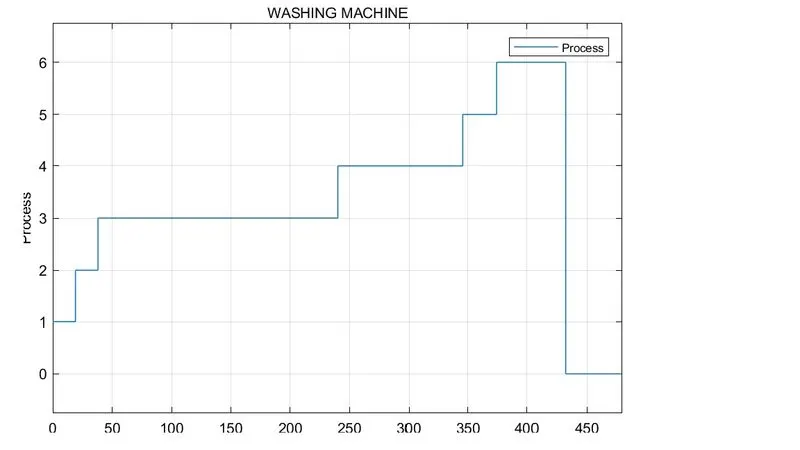
*Output is dispalyed by scope and lamps for their respective states.
Simulink model:
Output:
LED lamps:
Power ON 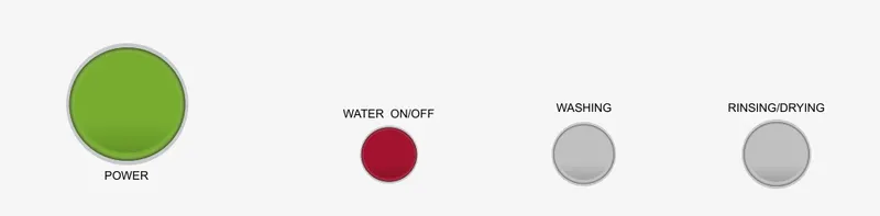
Water ON 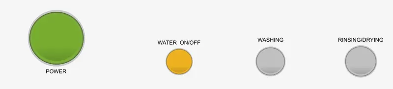
Washing 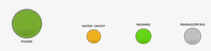
Rinsing/Drying 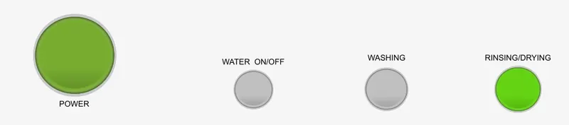
Power OFF 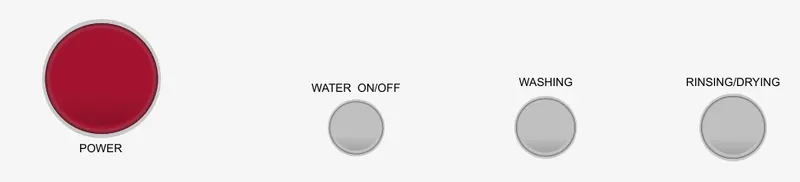
Conclusion:
*Thus the washing machine is controlled by the stateflow and also shown with the LED indicators.
________________________________________________________________________________________________________
2. Make a Simulink chart for the “Gear shift” logic as per below conditions:
Speed Range(kmph) Gear
0 to 15 1
16 to 25 2
26 to 40 3
41 to 60 4
Above 61 5
*Give speed input while the simulation is running & display the gear number.
ANS:
*Here we are controlling a gear box automatically by the the vehicle speed
The given speed and gear ranges are:
Speed Range(kmph) Gear
0 to 15 1
16 to 25 2
26 to 40 3
41 to 60 4
Above 61 5
Input:
It is given by slider gain (i.e speed)
Operation:
It is done in state flow with the required conditions.
Output:
It is shown by the respective gear LED.
Procedure:
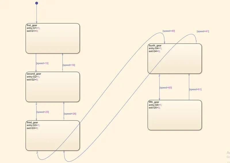
- Here the process is done by stateflow and the conditions between the states.
- Inside the chart, five states reperesenting their respective gears.
- Inside every state, we are defining the gears as 'G', when the flow enters the state then the respective gear activates by 'G1 = 1' and exits by 'G1 = 0'.
- The conditions direct the flow of states by,
- [speed>15] ; [speed<16]
- [speed>25] ; [speed<26]
- [speed>40] ; [speed<41]
- [speed>60] ; [speed<61]
Simulink Model:
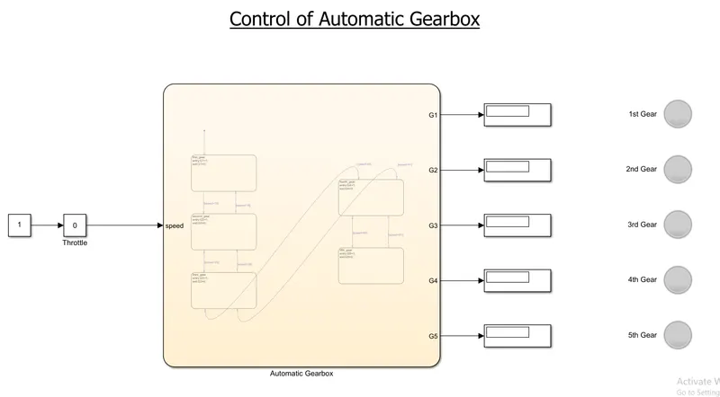
Output:
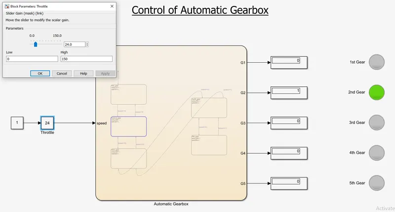
1. In (0-15kmph) speed range the gear ranges in;
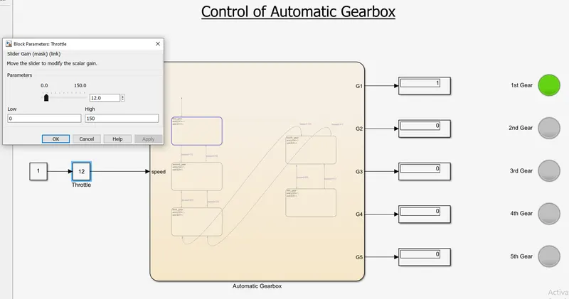
2. In (16-25kmph) speed range, the gear ranges in;
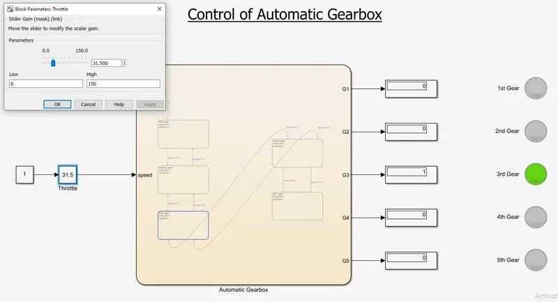
3. In (26-40kmph) speed range, the gear ranges in;
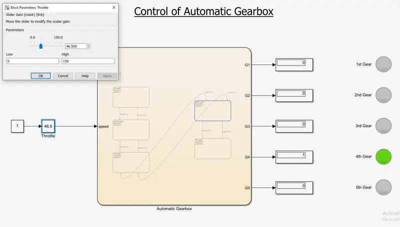
4. In (41-60kmph) speed range, the gear ranges in;
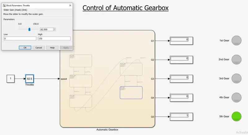
5. In (Above 61kmph) speed range, the gear ranges in;
Conclusion:
*For every different speed ranges, the gearbox automatically shifts to its particular gear with the help of stateflow.