Week 9:- 2D Detailing Challenge
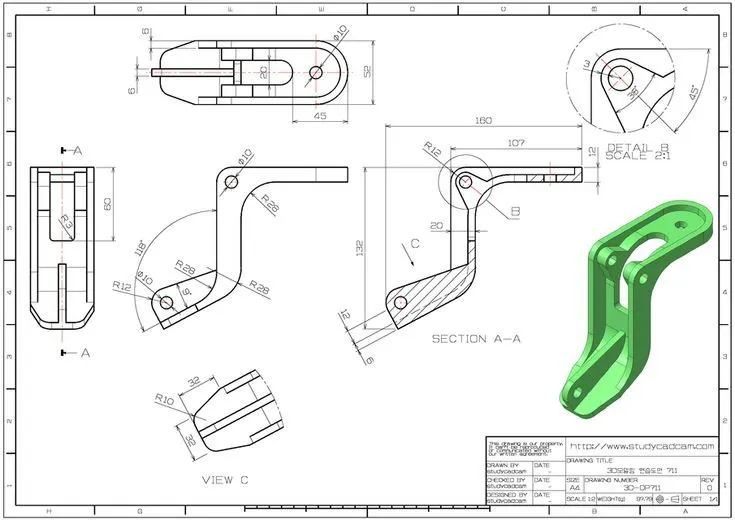
1) What are drawing templates?
- Drawing templates are essentially the drawing standards as per the customers specifications.
- Drawing templates are of a format that are used for detailing of different parts or units of the fixture.
- There are ‘n’ numbers of details, that are already available on the template and are useful for various manufacturing processes such as, machining finish, tolerances, surface treatments, material, name of the parts, name of the assemblies etc.
- Preparing a drawing template at the start of the project can help us save time as these templates can be used as a base model for detailing the different parts.
- Drawing templates also gives information about the angle of projection to be used, views to be considered, scaling of the drawing as per the part or unit.
Drawing templates tend to contain information such as:
- Scale
- Type of projection
- GD&T
- Quantity
- Tolerances
- Sheet size and number
- Project name
- Project code
- Part number
- Name of the company
- Mass
- Density
- Allowance
2) What do you understand by angle of projection?
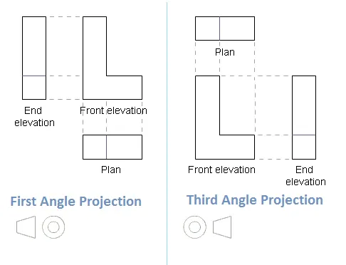
The angle of projection is a system that is used to represent a 3D object in a 2D plane. The projection system makes use if parallel line, to project a 3D object view onto a 2D plane. Following the rules of orthographic projection, to draw a projection view of a 3D object on a 2D plane, the horizontal plane is rotated in the clockwise direction.
There are 2 main types of orthographic projection systems used and they are:
- First Angle Projection
- Third Angle Projection
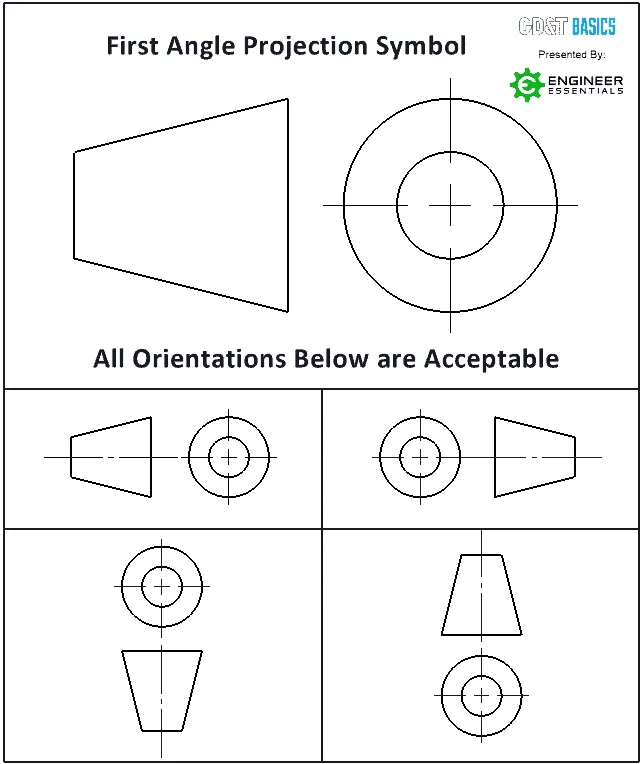
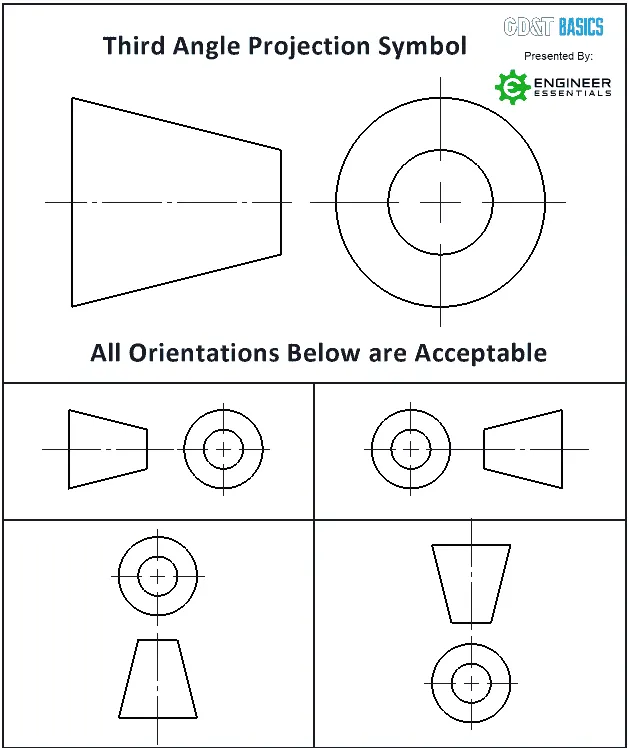
These are defined by unique symbols which can be marked on the drawing sheet to denote it to the next person looking at the drawing sheet so that they can understand which type of projection was used in the 2D drawing.
3) What is the first angle and third angle projection? Why do we not use the 2nd and 4th angle of projection?
First Angle Projection
In the first angle projection, the object is placed in the 1st quadrant. The object is positioned at the front of a vertical plane and top of the horizontal plane. First angle projection is widely used in India and European countries. The object is placed between the observer and projection planes. The plane of projection is taken solid in 1st angle projection.
Third Angle Projection
In the third angle projection, the object is placed in the third quadrant. The object is placed behind the vertical planes and bottom of the horizontal plane. Third angle projection is widely used in the United States. The projection planes come between the object and observer. The plane of projection is taken as transparent in 3rd angle projection.
The reason why the 2nd and 4th angle of projection is not used is due to the way the orthographic projections are taken. When the horizontal plane is rotated by 90 degrees in the clockwise manner, the top and front view of the object if placed in these quadrants will end up overlapping and this will cause a clash in the views and will be impossible to understand. Whereas in the first and fourth quadrant, when the horizontal plane is rotated by 90 degree, the front and top view remain on the vertical plane and away from each other and hence it is easy to understand. This is the reason why the second and fourth angle of projections are not used.
4) What is GD&T? What are the benefits of GD&T?
Geometric dimensioning and tolerancing (GD&T) is a language of symbols and standards designed and used by engineers and manufacturers to describe a product and facilitate communication between entities working together to produce anything.
GD&T uses a symbolic language to indicate how significantly the features in a part can deviate from the geometries listed in the design model. This will contain all required information and details such as dimensions, tolerances, symbols that denote the features.
Benefits of GD&T
- GD&T provides standardized design language for all entities to understand
- It also provides a clear and precise way for the customers, suppliers and production teams to communicate
- A method for calculating the worst possible case mating limits.
- Production and inspection process are repeatable because of the application of GD&T
- Assembly is assured from qualified production parts.
5) Explain all the symbols used in GD&T?
There are a total of 14 symbols that are used in GD&T to help other understand the drawings better and these are shown in the table below:
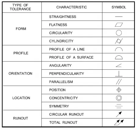
Form:
Form tolerances are individual characteristics of individual features, and therefore, are not referenced to datums. A form tolerance is a basic geometry tolerance and it helps define the shape of a feature.
Form tolerances can be stated by four characteristics that are Straightness, Flatness, Circularity and Cylindricity. Each defines the tolerance zone of geometric form to limit how far an actual surface is permitted to vary from its perfect shape.
Profile:
Profile tolerance is a control that defines a tolerance zone within which the surface of a feature must be contained. For specifying profile of a line, the tolerance zone is defined at an ideal cross-section. The profile of a surface tolernace is used to control the entire surface of a feature relative to a true three-dimensional surface, either for a single feature or a group of features, and may or may not be related to datums. Profile is the most powerful of all of the GD&T controls as it may be used to control only form, or form and orientation, or form, orientation, and location, or even size. In essence, all of the other geometric controls are a “subset” of the profile tolerance.
Orientation:
Orientation tolerance is a set of geometric tolerances that let you define the orientation for the feature relative to a referenced datum. This category of tolerance defines three types of characteristics, i.e. parallelism, perpendicularity, and angularity. These are used to control the “tilt” of features and are always associated with basic angle dimensions that are often used as a refinement of location.
Location:
Location tolerance is defined by position, profile, and runout. Position tolerance states the permissible variation in the location of a feature’s axis or center about its true (theoretically exact) position.
Runout:
Runout tolerance is a geometric tolerance that is specified for the parts designed surfaces of revolution relative to a datum axis. It is used to control a feature within how much variation is allowed when it is rotated 360 degrees about its datum axis. In other words, this tolerance type defines the range in which the feature can “wobble” in comparison to the datum axis.