Week 9:- 2D Detailing Challenge
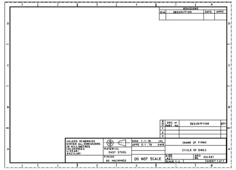
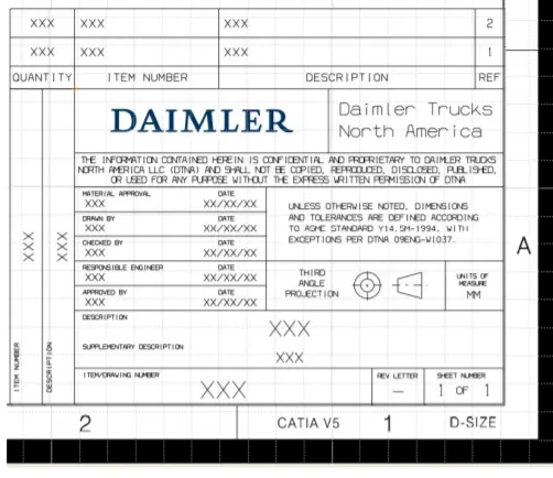
What are the Drawing templates?
Drawing Templates are basically the drawing standards as per customer’s specifications.
Drawing Templates are format that are used for detailing of different parts or units of the fixture.
There are ‘n’ numbers of details, that are already available on the template & are useful for various manufacturing processes, such as, machining finish, tolerances, surface treatments, material, name of the parts, name of the assemblies etc
Preparing a drawing template at the start of the project can help us save time, as these templates can be used as a start model for detailing for different parts.
Drawing templates also gives information about the angle of projection to be used, views to be considered, scaling of the drawing as per the part or unit.
What do you understand by Angle of projection?
Angles of projection are basically the view formats for orthogonal views of assemblies or parts.
First & Third angles of projection are majorly used in automotive standards.
Understanding the angles of projection help us to derive the actual image of 2D drawing.
It is also very important for various manufacturing processes for machine shop operators.
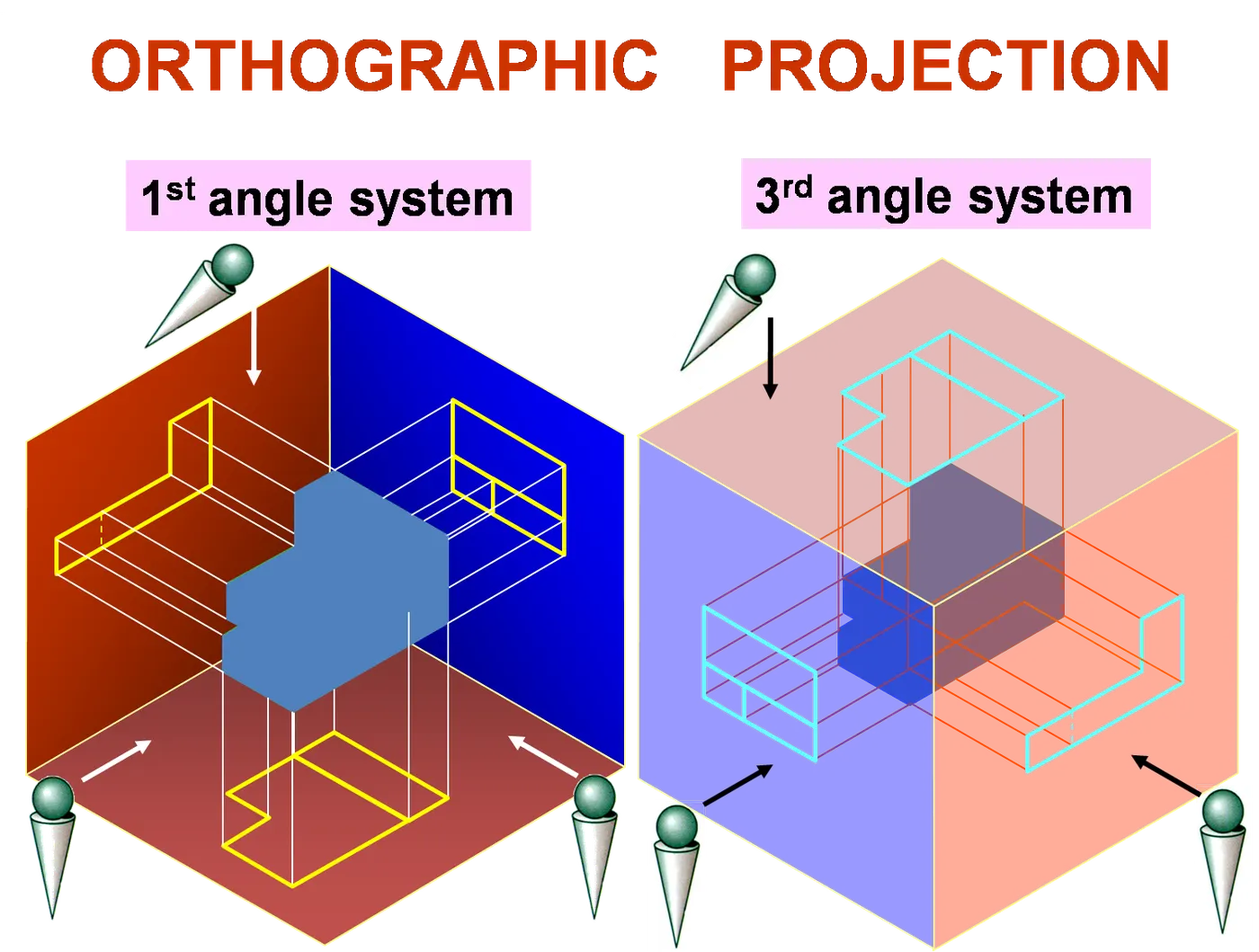
What is the First angle & Third angle projection? and why can't we use the 2nd and 4th angle of projection?
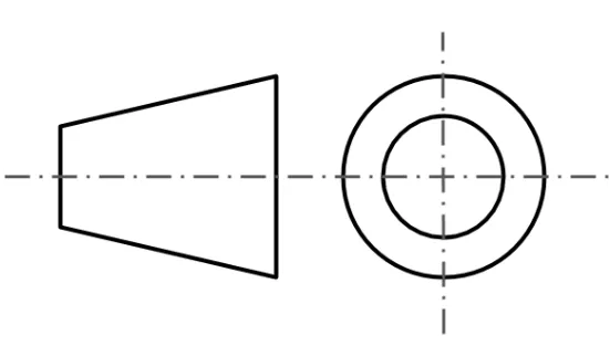
First Angle Projection
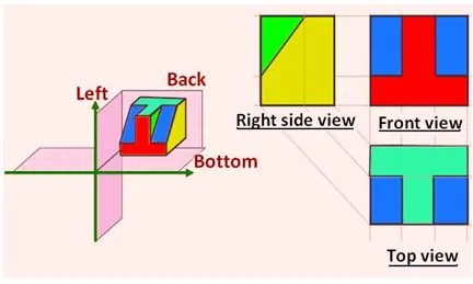
In this, the object is assumed to be positioned in the first quadrant.
The object is assumed to be positioned in between the projection planes and the observer.
The views are obtained by projecting the images on the respective planes.
Symbol:
Third Angle Projection
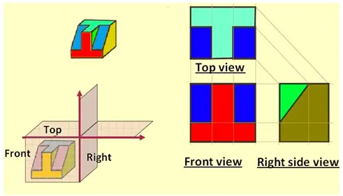
Here the object is assumed to be in the third quadrant. i.e., the object behind vertical plane and below the horizontal plane.
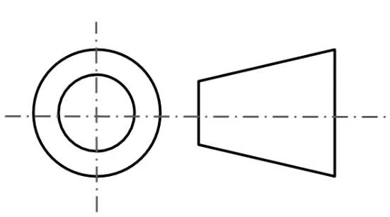
In this projection technique, placing the object in the third quadrant puts the projection planes between the viewer and the object.
Symbol:
We cannot use the 2nd and 4th angle of projection because:
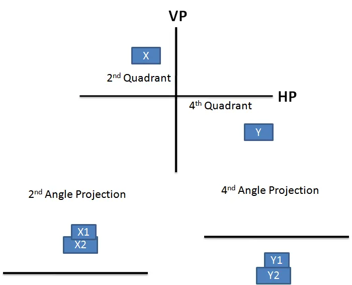
In Second quadrant, Vertical plane (VP) lies in between object and observer. Therefore front view of the object will lie on vertical plane whereas top view will lie on horizontal plane. As per rule of projection when horizontal plane is rotated 90 degree in clockwise direction, top and front view will overlap.
Overlapping projection views create confusion in the drawing. Therefore 2nd angle projection system is not used.
Similarly when object is placed in 4th quadrant both top and front view will overlap. Therefore fourth angle projection is also not used.
What is GD&T? What are the benefits of GD&T?
Geometric Dimensioning and Tolerancing (GD&T) is a language of symbols and standards designed and used by engineers and manufacturers to describe a product and facilitate communication between entities working together to produce something.
By deepening our knowledge around how to create a well-structured GD&T, we will improve communication with our machine shop and ensure everyone involved is speaking the same language.
The benefits of Geometric Dimensioning and Tolerancing (GD&T) are:
- A standardized design language
- A clear and precise way for the customers, suppliers, and production teams to communicate
- A method for calculating the worst-case mating limits
- Production and inspection processes are repeatable
- Assembly is assured from qualified production parts
Explain all the symbols used in GD&T?
Symbols or Geometric Characteristics are what most often come to mind when people think about GD&T. There are a total of fourteen GD&T characteristics, and the symbols that represent them are shown in the symbol “sheet” below.
These symbols are placed in the first compartment of a feature control frame and define the type of tolerance that is to be applied to the feature. The characteristics are grouped together into types of tolerance: form, orientation, location, runout, and location of derived median points. The primary use and description of each characteristic is also shown.
GD&T is a feature-based system, and parts are composed of features. Geometric tolerances are applied to features by feature control frames. The most frequently used tolerance categories are form, orientation, and location; therefore, the ten associated symbols are the most utilized of the fourteen total GD&T symbols.
Form tolerances control the “shape” of features and are often used as a refinement of size.
Orientation tolerances control the “tilt” of feature and are always associated with basic angle dimensions, often used as a refinement to location. If applied to surfaces, orientation tolerances also control form.
Location tolerances control location and are always associated with basic linear dimensions. Position locates and orients the median plane or axis of features of size. Profile locates feature surfaces. Profile is the most powerful characteristic of all, and also controls orientation and form.