Week 9:- 2D Detailing Challenge
- What are the Drawing templates?
Drawing template is the formate that consists of all the data of the particular part design or assembly and it gives the information of the part dimensions and location, shape structure relative to the parts surface finish for the parts can be shown .once the 3D design was completed and it is converted to 2d drawing for the manufacturing it can also show the page layout and angle of projection and
Drawing templates are formats that are used for different detailing of different parts and units.
There are ‘n’ number of detailing they are already available on the template & useful for material, name of the part, name of the assembly, etc
The drawing template also gives information about the angle of projection to be used, views to be considered, scaling of the drawing as per the part or unit.
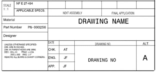
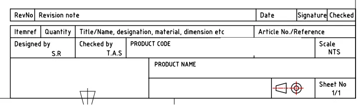
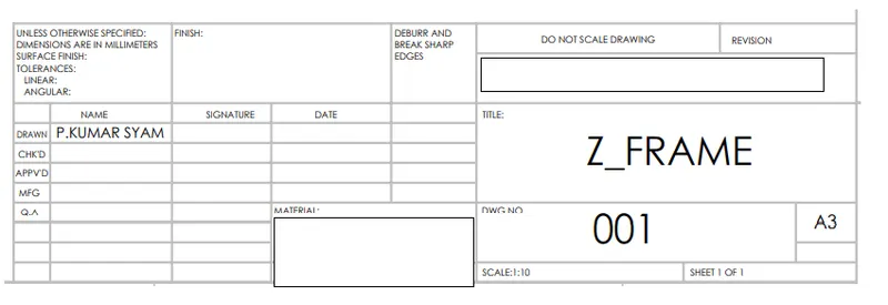
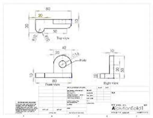

fig some Drawing Templates
Some of the information's of the Drawing Template :
- Company name.
- Project Name.
- Sheet Size.
- Sheet Number.
- The angle of Projection.
- Revision number/letter(if it's a revision drawing).
- Signature or name of drawn by. Checked by, responsible engineer and approved by.
- Parts detail.
- Quantity.
- Additional notes (surface finish, Heat treatment, Material detail. Etc.)
- Scale, Date Unit of measurement.
Note: Above standards can vary as per company standards.
2, What do you understand by Angle of projection?
The angle which an observer draw an object to convert it from 3D to 2D planes such as real object images of the plane paper is known as an angle of projection
The angle of projection is the view format for orthogonal views of assemblies or parts
Orthographic projections
Orthographic projection uses multiple views of an object, from points of view rotated about the object's center through increments of 90 degrees. In the first angle projection, each view of the object is projected in the direction (sense) of sight of the object.
Horizontal plane(H.P), vertical plane(V.P), SIDE, or Profile plane are the two reference planes
Difference views of the plane front (FV), Top view(TV), AND SIDE VIEW(SV)
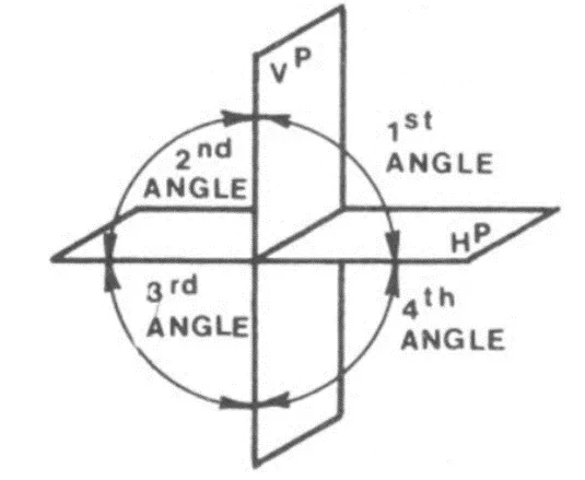
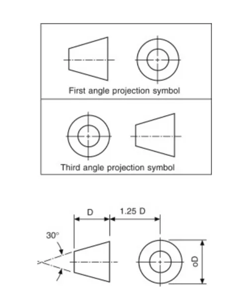
Fig All four quadrants
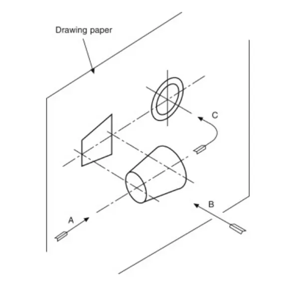
Fig First angle projection
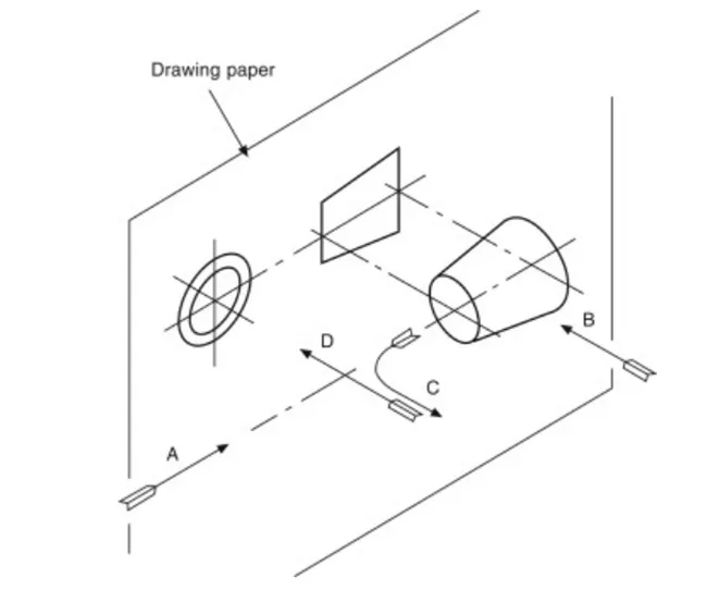
Fig Third angle projection
Every design can be shown in the first angle and 3rd angle projection in general 2nd and 4th angle projections are not used because of the 2nd and 4th quadrants their projection plane are not visual
3. What is the First angle & Third angle projection? and why can't we use the 2nd and 4th angle of projection?
The orthographic projection system is used to represent a 3D object in a 2D plane. The orthographic projection system utilizes parallel lines, to project 3D object views onto a 2D plane. According to the rule of orthographic projection. To draw a projection view of a 3D object on a 2D Plane. The horizontal plane is rotated in the clockwise direction.
Types of Orthographic projection systems are first angle and third angle projection.
- First Angle Projection:
In the first angle projection, the object is placed in the 1st quadrant. The object is positioned at the front of a vertical plane and top of the horizontal plane. First angle projection is widely used in India and European countries. The object is placed between the observer and projection planes. The plane of projection is taken solid in 1st angle projection.
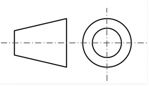
first Angle Projection
- Third Angle Projection:
In the third angle projection, the object is placed in the third quadrant. The object is placed behind the vertical planes and the bottom of the horizontal plane. Third angle projection is widely used in the United States. The projection planes come between the object and the observer. The plane of projection is taken as transparent in 3rd angle projection.
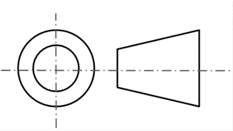
Fig Third angle projection
|
SR.NO |
First Angle Projection |
Third Angle Projection |
|
1 |
The object is placed in the first quadrant. |
The object is placed in the third quadrant. |
|
2 |
The object is placed between the plane of projection and observer. |
The plane of projection is placed between the object and the observer. |
|
3 |
The plane of projection is opaque. |
The plane of projection is transparent. |
|
4 |
The front view is at the top of the horizontal axis. |
Front view at the bottom of the horizontal axis. |
|
5 |
Top view at the bottom of the horizontal axis. |
Top view at the top of the horizontal axis. |
|
6 |
The right view is at the left side of the vertical axis. |
The right view is at the right side of the vertical axis. |
|
7 |
The left view is at the right side of the vertical axis. |
The left view is at the left side of the vertical axis. |
|
8 |
It is widely used in Europe, India, Canada. |
It is widely used in United State and Australia. |
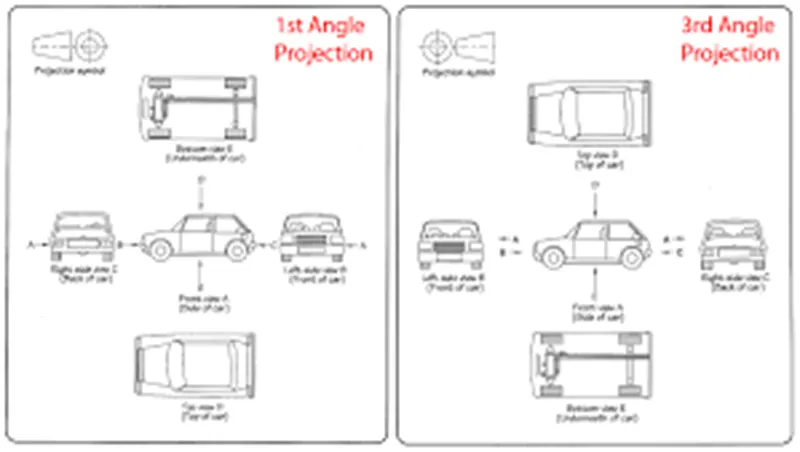
Fig Difference Between 1st and 3rd angle Projections
In Mechanical Engineering, drawings are made either in first angle projection or in third angle projection. We do not make drawings in second or fourth angle projection. We will discuss the reason behind doing so in this article.
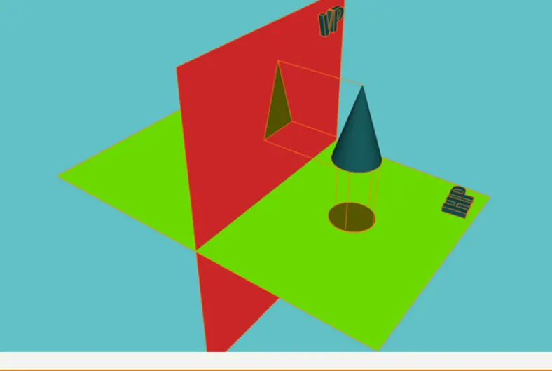
Let us first understand the concept behind the angle projection system. Imagine you have Vertical Plane (VP) and Horizontal Plane (HP) (Perpendicular to each other), now we have 4 quadrants. For the 1st angle projection system, we place an object in the 1st quadrant, for the 2nd angle projection system, we place an object in the 2nd quadrant, and so on.
In the second quadrant, the Vertical plane (VP) lies in between object and observer. Therefore, the front view of the object will lie on a vertical plane whereas the top view will lie on a horizontal plane. As per the rule of projection when the horizontal plane is rotated 90 degrees in a clockwise direction, the top and front views will overlap.
Overlapping projection views create confusion in the drawing. Therefore 2nd angle projection system is not used.
Similarly, when the object is placed in the 4th quadrant both the top and front view will overlap. Therefore, fourth angle projection is also not used.
To sum up, because of overlapping of front and top views 2nd and 4th angle projections are not used. First and third angle projection systems are recommended for orthographic projections
4. What is GD&T? What are the benefits of GD&T?
Geometric Dimensioning and Tolerancing (GD&T) is a system for defining and communicating engineering tolerances and relationships. It uses symbolic language on engineering drawings and computer-generated three-dimensional solid models that explicitly describe nominal geometry and its allowable variation. It tells the manufacturing staff and machines what degree of accuracy and precision is needed on each controlled feature of the part. GD&T is used to define the nominal (theoretically perfect) geometry of parts and assemblies, to define the allowable variation in form and possible size of individual features, and to define the allowable variation between features.
Dimensioning specifications define the nominal, as-modeled, or as-intended geometry. One example is a basic dimension.
Tolerancing specifications define the allowable variation for the form and possibly the size of individual features, and the allowable variation in orientation and location between features. Two examples are linear dimensions and feature control frames using a datum reference.
The language of geometric dimensioning and tolerancing can be intimidating at first, but when used properly, it can yield many advantages:
- The standardized, international system
- More flexibility, particularly for complex shapes
- Allows cylindrical tolerance zones
- Datum is clearly defined
- Based on the fit and function of a part or assembly
- Eliminates the need for many notes
- Allows for more tolerance
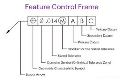
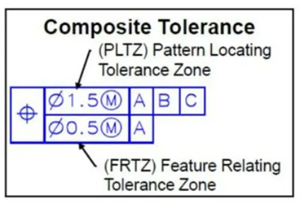
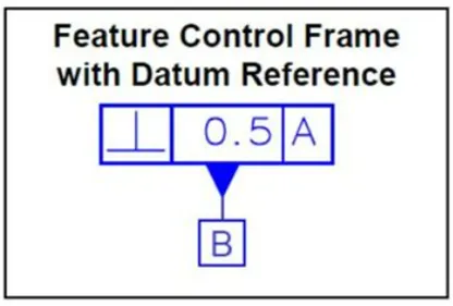
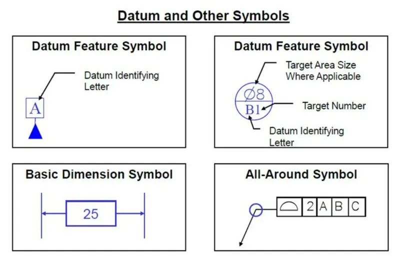
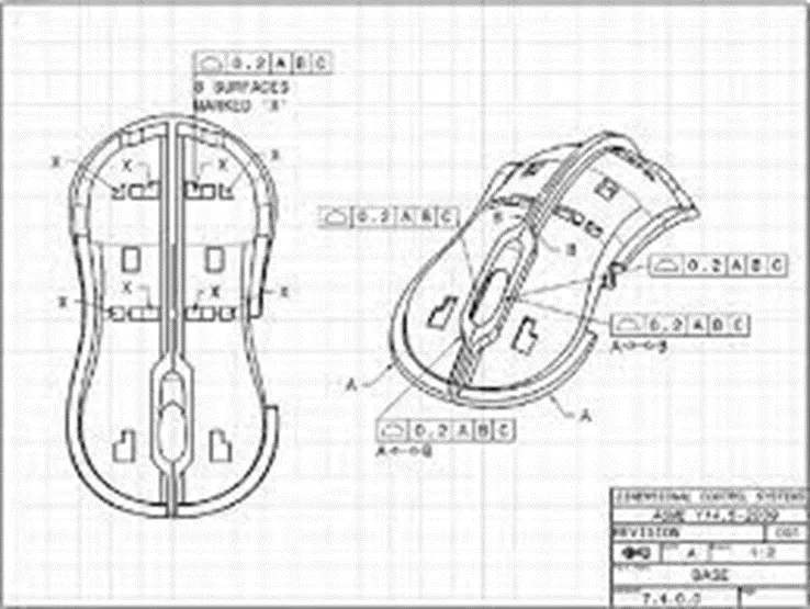
Fig GD&T final Drawing Template
5. Explain all the symbols used in GD&T?
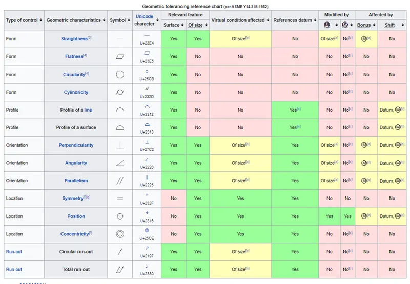
Orientation Tolerances control the "tilt" of feature and are always associated with basic angle dimensions. often used as a refinement to location applied to surfaces orientation tolerances also control form
Location Tolerance control location and are always associated with basic linear dimensions Position locates and orients the median plane oasis of features of size Profile locates feature surfaces Profile is the most powerful characteristics of all and also controls orientation and form
Runout is how much one given reference feature or feature varies concerning another datum when the part is rotated 360 deg around the datum axis. It essentially controls a circular feature and how much variation it has with the rotational as sis Runout can be called out on any feature that is rotated about the assist is essentially how much wobble occurs in the one part feature when referenced to another
Some other symbols used in GD&T
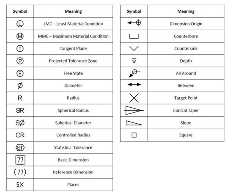
Least material condition (LMC): The condition where the feature contains the least material within the stated limits of size(eg small pin or large hole).
Maximum material condition (MMC): The condition where the feature contains maximum material within the stated limits of size (eg large pin /small hole).
Projected tolerance zone: The projected tolerance zone applies to a feature's protrusion In most cases, the zone to which geometric tolerances are applied is limited to the range of features specified in the drawing In contrast to this indication using the projected tolerance zone can specify a virtual zone for the specified features mating part.
Basic dimensions: Basic dimensions are theoretically exact numerical values used to define. size, orientation, or location of a part or feature Basic dimensions are usually shown on a drawing enclosed in a box. but they can also be invoked by referencing a standard or by another on the drawing,
Free state: Adds the free state modifier, to indicate that the geometric tolerances apply in the unrestrained condition. This modifier is only applicable for not right parts for which there is a note that indicates that tolerances are specified for the restrained state.