Week 9:- 2D Detailing Challenge
1.
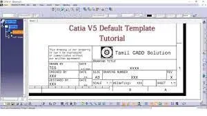
drawing templates are used for converting the 3D models in 2D orthographic or isometric views in order to dpict dimensions ,the nomenclature of various subparts,the part or component name.The drawing templates used can be of CAD software inbulit or the separate template can be created by user according to the rquirements.
The drawing templates may have the total keysheet details of the BIW fixture or it may have the various details like the BOM,designing details,the info about the drawer,checker,approver.The templates have the details about the how much sub components are present in the the object.The details about the 2D dimensions of the objects are present in the template.
The templates generally used for can be used for various types according standards set by particular industry standards.
but the above data remains the same for every operations.
the catia templates are used for 2D drafting.
2.
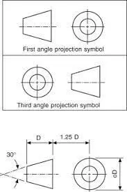
The angle at which an observer draw an object to convert it from 3D to 2D plane such as real oject image to plane paper is known as angle of projection.the are two types of angles of projection like first angle of projection and third angle of projection.
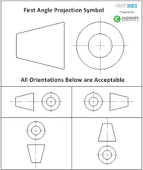
1.First angle of projection.
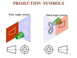
2.Third angle of projection.
3.
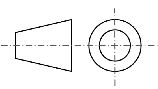
a.First angle of projection.
In the first angle projection, the object is placed in the 1st quadrant. The object is positioned at the front of a vertical plane and top of the horizontal plane. First angle projection is widely used in India and European countries. The object is placed between the observer and projection planes. The plane of projection is taken solid in 1st angle projection.
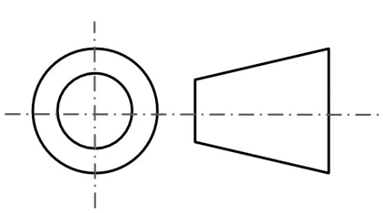
b.Third angle of projection.
In the third angle projection, the object is placed in the third quadrant. The object is placed behind the vertical planes and bottom of the horizontal plane. Third angle projection is widely used in the United States. The projection planes come between the object and observer. The plane of projection is taken as transparent in 3rd angle projection.
4.Geometric Dimensioning and Tolerancing (GD&T) is a language of symbols and standards designed and used by engineers and manufacturers to describe a product and facilitate communication between entities working together to produce something.
- Standardized, international system.
- More flexibility, particularly for complex shapes.
- Allows cylindrical tolerance zones.
- Datums are clearly defined.
- Based on the fit and function of a part or assembly.
- Eliminates the need for many notes.
- Allows for more tolerance.
5.
symbols based on .
locationbased=Position is one of the most useful and most complex of all the symbols in GD&T. The two methods of using Position discussed on this page will be RFS or Regardless of Feature Size and under a material condition (Maximum Material Condition or Least Material Condition). Position is always used with a feature of size.
Datums in GD and T=A datum is theoretical exact plane, axis or point location that GD&T or dimensional tolerances are referenced to. You can think of them as an anchor for the entire part; where the other features are referenced from. A datum feature is usually an important functional feature that needs to be controlled during measurement as well.
profile of surface=
Profile of a surface describes a 3-Dimensional tolerance zone around a surface, usually which is an advanced curve or shape...
maximum material condition=
Profile of a surface describes a 3-Dimensional tolerance zone around a surface, usually which is an advanced curve or shape...
flatness=GD&T Flatness is a common symbol that references how flat a surface is regardless of any other datum’s or features. It comes in useful if a feature is to be defined on a drawing that needs to be uniformly flat without tightening any other dimensions on the drawing. The flatness tolerance references two parallel planes (parallel to the surface that it is called out on) that define a zone where the entire reference surface must lie.
concentricity=Concentricity, sometimes called coaxially, is a tolerance that controls the central axis of the referenced feature, to a datum axis....
perpendicularity=Perpendicularity is a fairly common symbol that requires the referenced surface or line to be perpendicular or 90° from a datum surface or line...
Runout=Runout is how much one given reference feature or features vary with respect to another datum when the part is rotated 360° around the datum axis.
parallellism=Parallelism is a fairly common symbol that describes a parallel orientation of one referenced feature to a datum surface or line...
circularity=The circularity symbol is used to describe how close an object should be to a true circle.
straightness=The standard form of straightness is a 2-Dimensional tolerance that is used to ensure that a part is uniform across a surface or feature. Straightness can apply to either a flat feature such as the surface of a block, or it can apply to the surface of a cylinder along the axial direction. It is defined as the variance of the surface within a specified line on that surface.
total runout=
Total Runout is how much one entire feature or surface varies with respect to a datum when the part is rotated 360° around the datum axis...
cylindricity=The Cylindricity symbol is used to describe how close an object conforms to a true cylinder...
Angularity=Angularity is the symbol that describes the specific orientation of one feature to another at a referenced angle.
LMC=Least material condition is a feature of size symbol that describes a dimensional or size condition where the least amount of material (volume/size) exists within its dimensional tolerance.
profile of line=Profile of a line describes a tolerance zone around any line in any feature, usually of a curved shape...