Worm Gear Analysis Using Ansys Workbench
OBJECTIVE
- To assign the structural steel material to the worm gear and worm wheel.
- To assign the joints.
- To mesh the model.
- To apply the boundary condition.
- To collect the results and interpret.
PROCEDURE
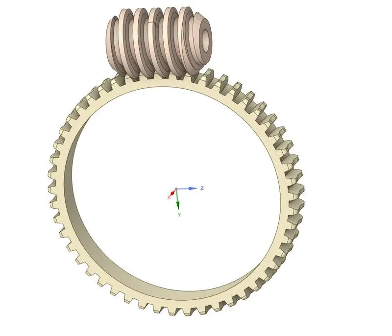
This simulation was an analysis of worm gear and worm wheel. The model can be seen in the figure below. The simulation seems to be transient-structural, therefore, it had to solve using the transient-structural module of Ansys. For solving the problem, the wheel was cut in half to reduce the number equation to solve.
 |
|
Figure 1: Worm and worm wheel model in Ansys GUI. |
The Mesh section of the Transient Structural module was opened. In that, the material of all the parts was set to structural steel (default). Further, the automatically detected contacts by Ansys were modified slightly. The number of contact faces was increased and the behavior of contact was changed to frictionless.
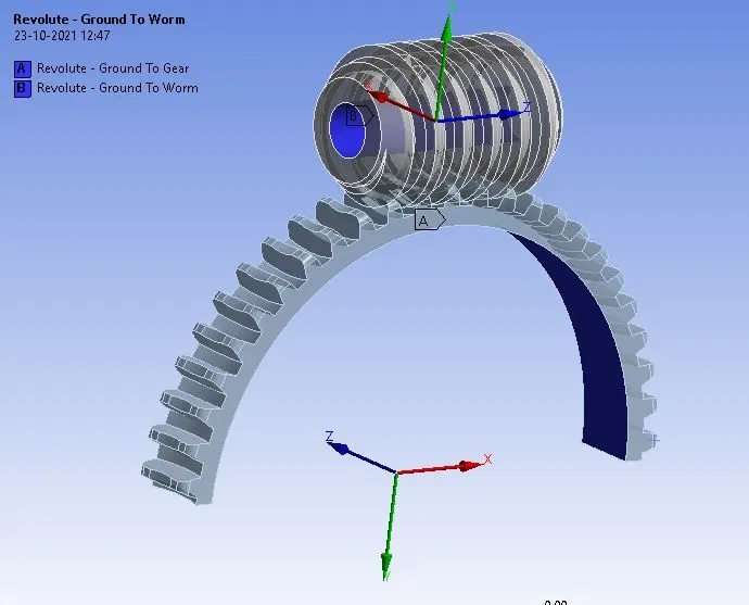
A revolute joint was defined for both the worm and worm wheel.
 |
|
Figure 2: Revolute joint for worm and worm wheel. |
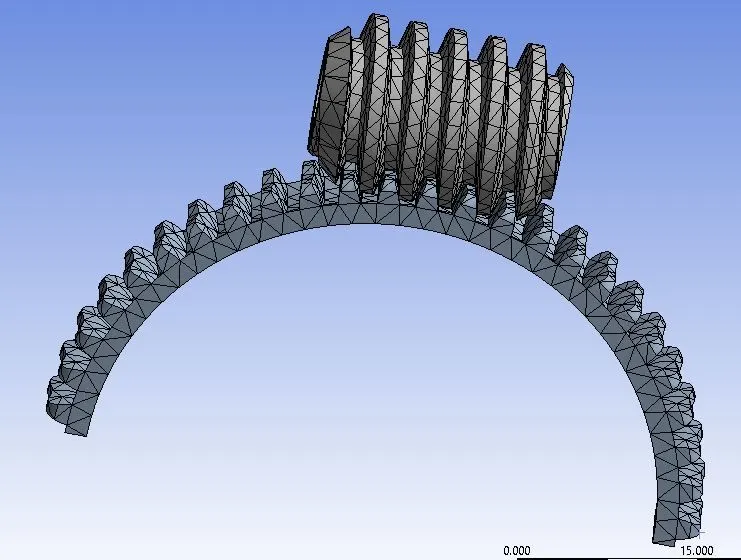
Next, the mesh was created for the model, as shown in the figure below.
 |
|
Figure 3: Meshing of the model. |
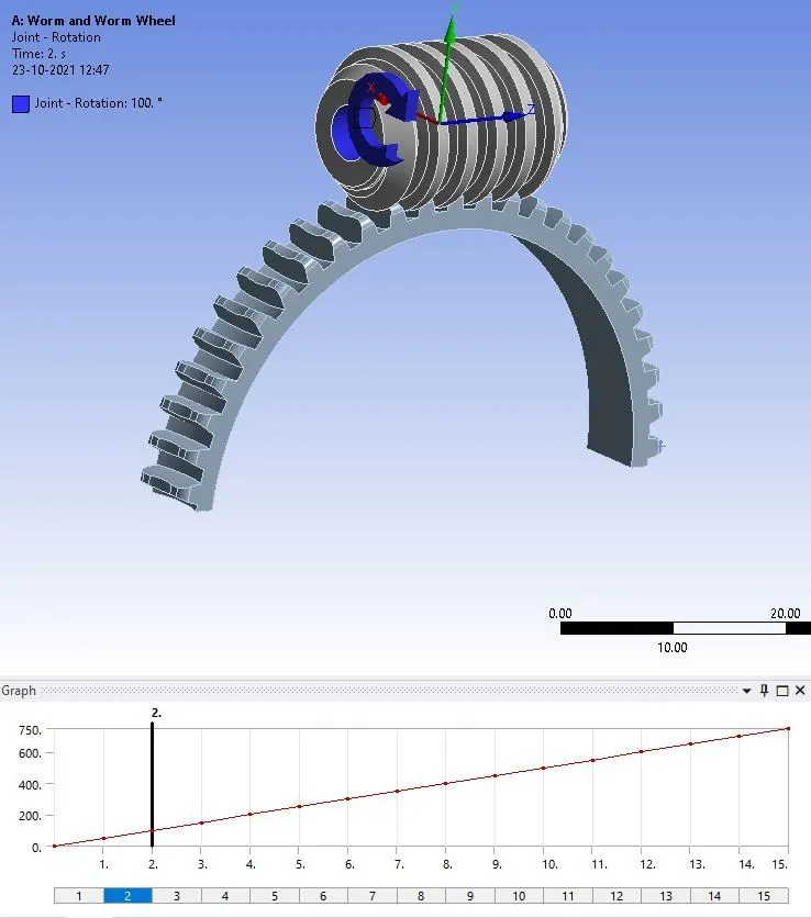
The analysis was solved in 15 steps. In boundary conditions, the rotation was applied to the worm, as shown in the figure.
 |
|
Figure 4: Rotation applied to the worm. |
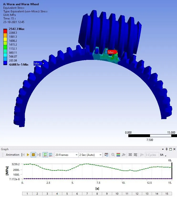
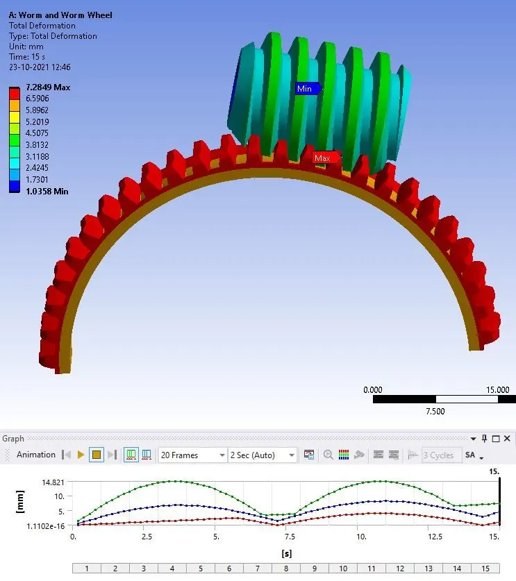
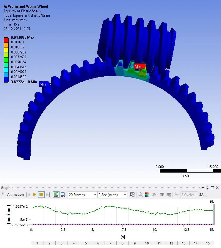
In the solution, the results were requested for the equivalent stress, equivalent elastic strain, and total deformation. All the results are shown in the figures below.
 |
|
Figure 5: Equivalent stress in the model, with maximum stress of 3239.2 MPa, on gear tooth. |
 |
|
Figure 6: Total deformation in the model with maximum deformation of 14.821 mm, at gear. |
 |
|
Figure 7: Equivalent elastic strain in the model with the maximum magnitude of 0.013 mm/mm. |
CONCLUSION
This simulation was performed to study the procedure of simulating the worm and worm wheel model. In this model, a revolute joint was applied to both the worm and worm wheel. And in the boundary conditions, a rotation was applied to the worm gear. In the results, it was observed that the stress generation is more on the wheel part than the worm part.