Week 8 Worm Gear Challenge
-
Objective: To perform transient structural analysis on the given worm gear assembly model.
-
Procedure:
Open the transient structural analysis system in the Project schematic. The material used for the analysis is structural steel which is available in the material library. Now proceed to import the geometry. Import the Geometry. Open the Geometry in SpaceClaim. Ensure the geometry is properly imported by doing quick visual inspection. The geometry is properly imported as observed.
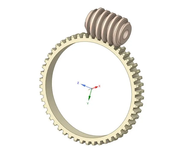
Now considering the limits of the academic version of the software, the analysis is to be performed considering only half gear portion. Delete the other half portion.
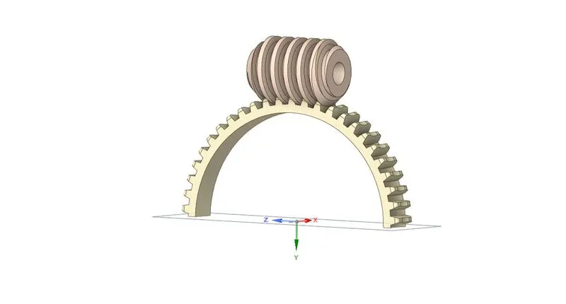
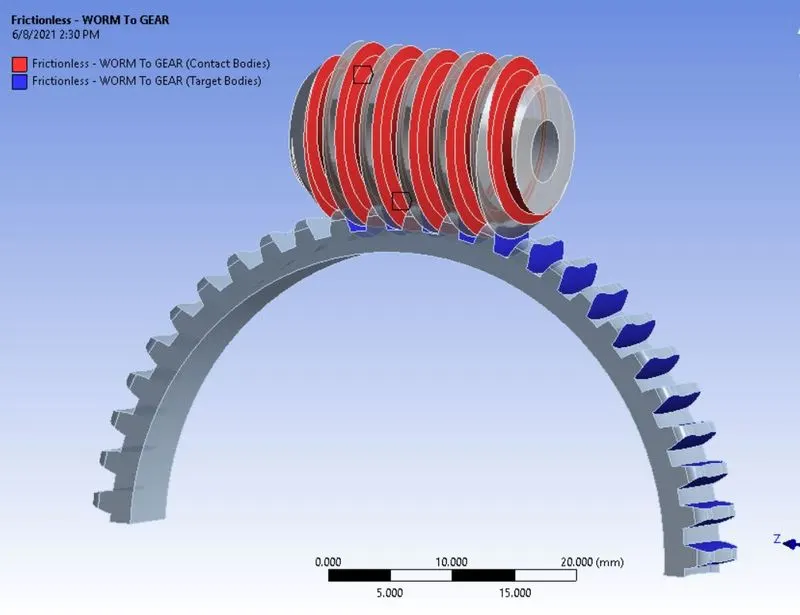
We will rotate the worm and the motion will be transferred to the gear as the worm rotates. Update and open the mechanical module. The material assigned for the model is Structural Steel. The Ansys automatic
contact detection has detect some initial contact between the members. Update the contacting faces that will be in contact during the simulation. The type of contact used is Frictionless.
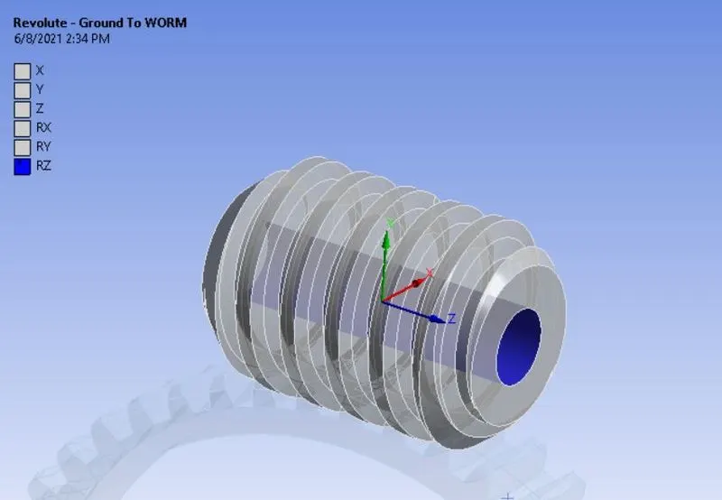
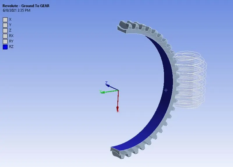
Insert a Body-Ground type revolute joint for both the gear and the worm, so that they are free to rotate. Go to Connections > Insert > Joint. Select the joint type as revolute and define the joint for the gear and
worm.
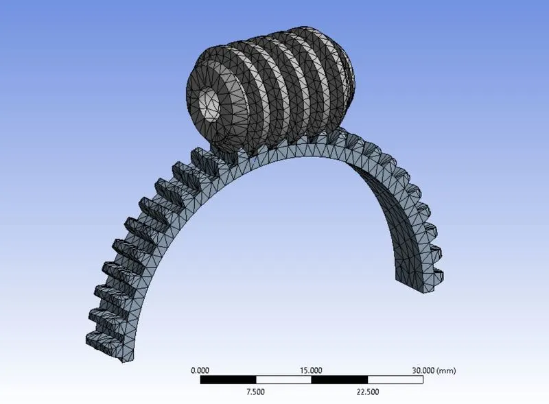
The component is meshed with element size of 1.5 mm. Adaptive sizing is turned off for meshing and the component is meshed.
The analysis is to be completed in 30 steps. In the analysis settings, enter the no. of steps = 30. Initial time step used is 0.2s, minimum time step used is 0.2s and the maximum time step used is 0.5s. Weak
springs is set to program controlled. Large deflection is turned on. Carry over time step is turned on.
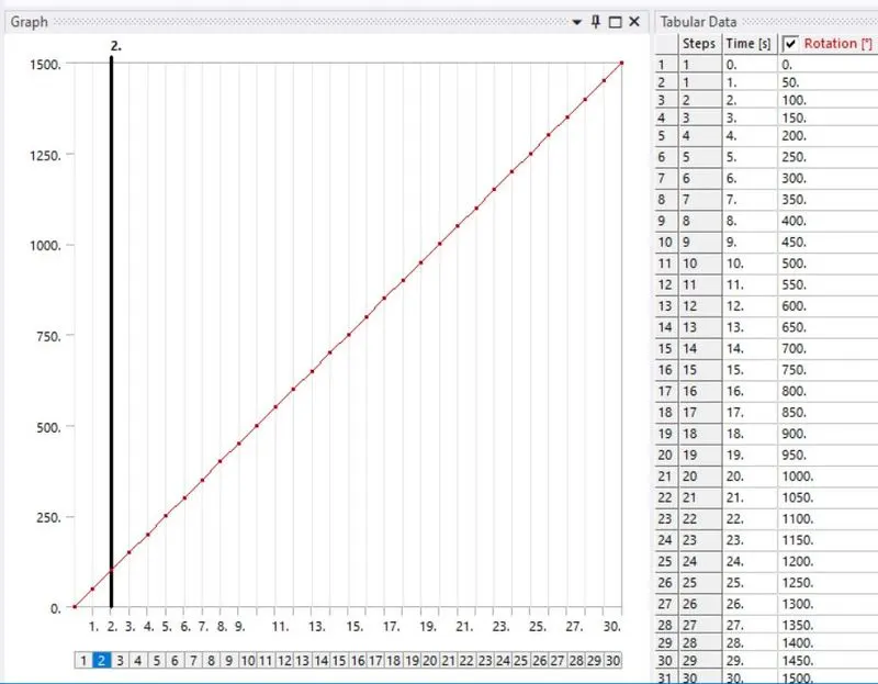
Now insert joint load for the worm. Go to transient > Insert > Joint Load. Select the Ground to worm joint. Set the type to rotation. For magnitude, enter the data in tabular form as shown below:
The case set up is complete. List the required results and run the simulation.
- Results:
Equivalent Stress in the model:
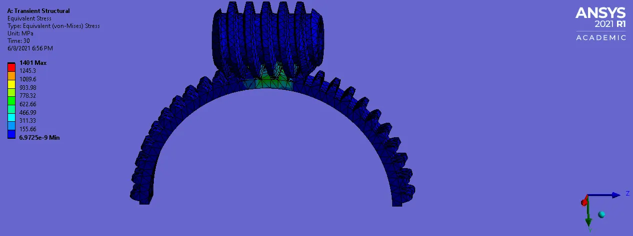
Max stress of 1401 Mpa is observed in the model.
Equivalent Strain in the model:
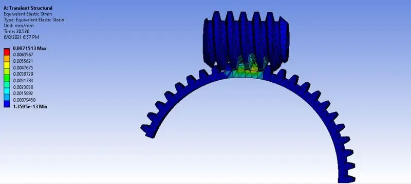
Max equivalent strain of 0.007 is observed in the model.
Total Deformation in the model:
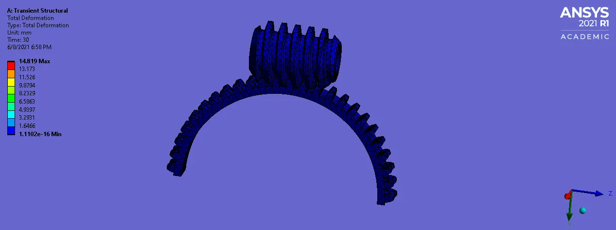
Max deformation of 14.81 mm is observed in the model.
- Conclusion: Thus the given worm gear assembly is successfully simulated and the area of maximum stress is identified to be on the gear. Max strain and deformation observed is also maximum on the gear
compared to worm.