Week 8 Worm Gear Challenge
Aim: To perform a transient structural analysis on a worm gear assembly.
Principle:
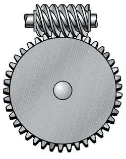
A worm gear is a gear consisting of a shaft with a spiral thread that engages with and drives a toothed wheel. Worm gears are an old style of gear and a version of one of the six simple machines. A worm gear is a screw butted up against what looks like a standard spur gear with slightly angled and curved teeth.
It changes the rotational movement by 90 degrees, and the plane of movement also changes due to the position of the worm on the worm wheel (or simply "the wheel"). They are typically comprised of a steel worm and a brass wheel.
Procedure:
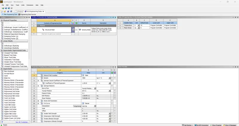
The analysis we are doing is a Transient Analysis, Select Transient analysis from the ANSYS workbench
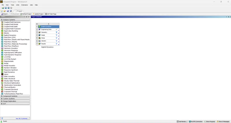
Open Engineering Data and from the Engineering services, Structural steel is selected as the material
Since the model is already provided we import the model in the geometry SpaceClaim, The model provided is a full, and the bottom part of the gear is removed to reduce the analysis time
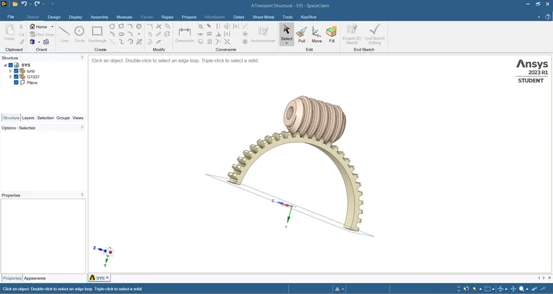
Once the Geometry is updated select the model option and click Edit
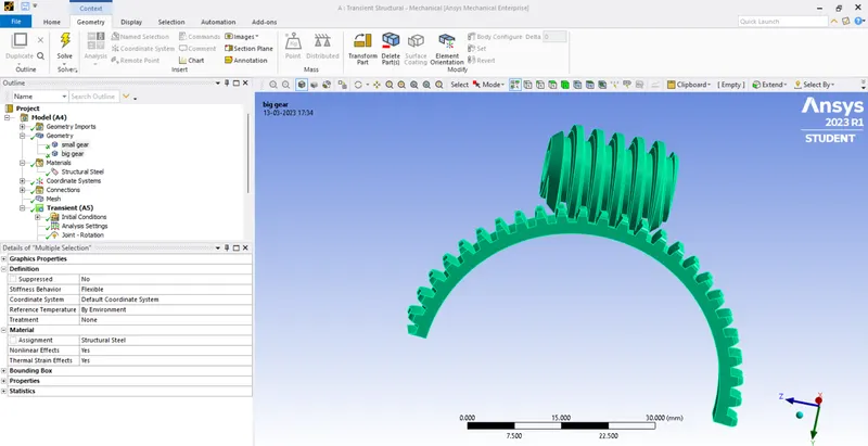
Structural Steel as the material in the material properties
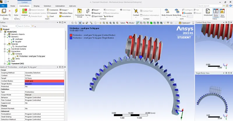
Contacts have been established between the small gear and the big gear and the type of contact is frictionless
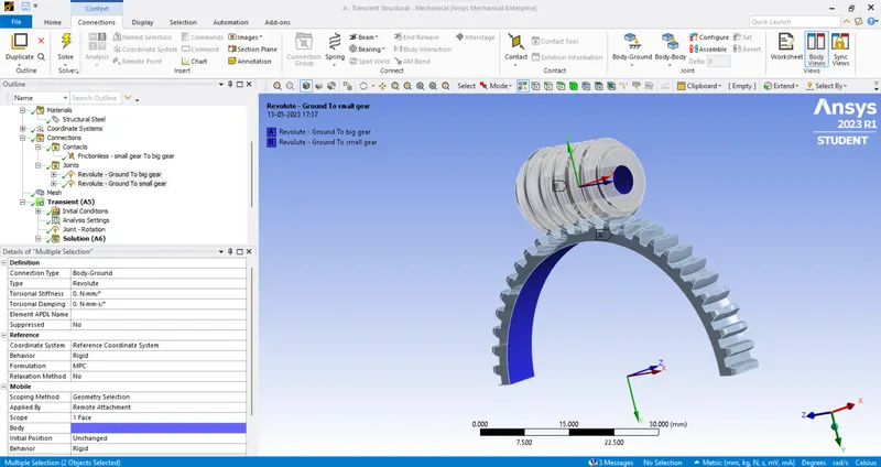
The revolute joint is given for the big gear and small gear
Meshing on the Component
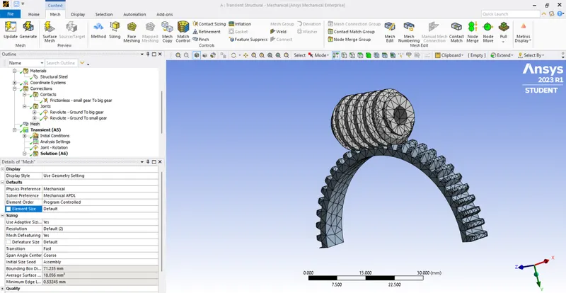
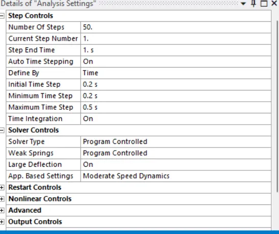
Analysis Settings
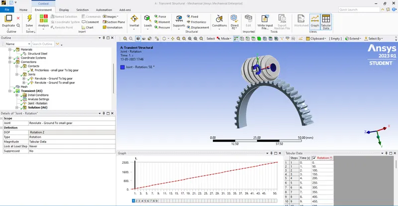
For Loading the Worm is applied Joint Rotation (Revolute- Ground to Worm), in which a total of 50 steps are applied for analysis, each step applied 50 degrees of rotation in each step.
No of Steps: 50
Carry Over Time Step: ON
Initial Time Step: 0.2 s
Minimum Time Step: 0.2 s
Maximum Time Step: 0.5 s
Large Deflection: ON
Results:
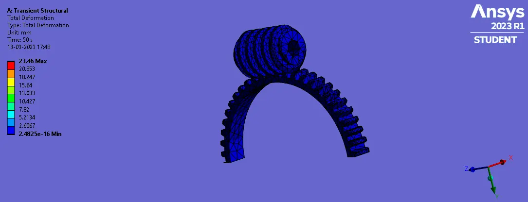
Total eformation
Maximum Deformation:23.46mm
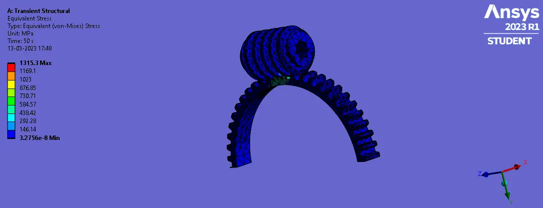
Equivalent Stress
Maximum Stress:1315.3Mpa
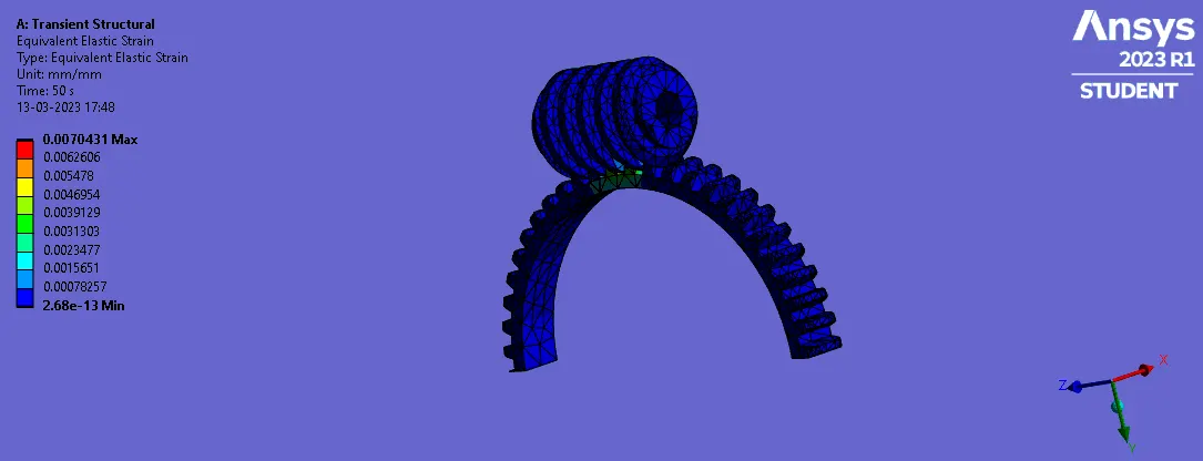
Equivalent Strain
Maximum Strain:0.0070431